54733-10BA2L
2 – 180 02.2017
2 Installation Volume 2
2.4 Detector Assembly
Make sure that
– the detector or the source fixtures do not obstruct the beam
path.
– there are no pipes, flanges, stirrers or other installations in the
beam path.
Only installations that have already been taken into account in plan-
ning the measurement configuration are permitted. Otherwise, the
curve is no longer linear; there may even be sections in the mea-
surement range where the measured values do not change.
2.4.1 Rod Detector with and without Water Cooling
The rod detector is mounted vertically on the outside of the vessel.
The top point of the effective detector length is marked by a mark-
ing groove, which also defines the top point of the measuring range
that can be covered. Please note the dimensional drawings of the
rod detector (page 2-243).
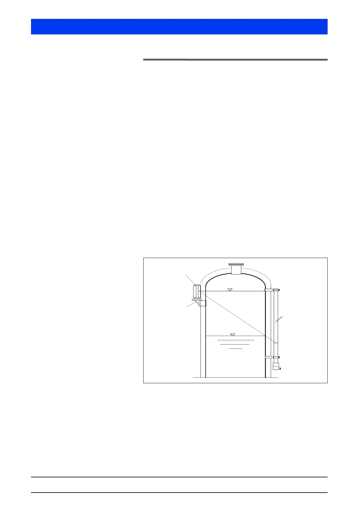
As shown in Fig. 2-2, the rod detector is mounted outside the
marking grooves, with one fixing clamp each at the top and at the
bottom. The distance from the center of the detector to the surface
of the vessel or the surface of a thermal insulation is about 100
mm. The clamps have to be arranged so that no heat is transferred
to the detector.
Fig. 2-2 Rod detector installation, example with point source
Max
Min
Support
Montagesockel
Point Source Shielding
Punktstrahler-Abschirmung
Rod Detector
Stabdetektor
←
Marking Groove
Markierungsrille
←
Marking Groove
Markierungsrille