54733-10BA2L
2 – 292 02.2017
6 Accessories Volume 2
6.2 Limit Switches for Pneumatics
Installation and setup instructions
for limit-switch box by KINETROL …
-003U Ex ed IIC T6 and
… -004U
If the limit-switch box … -003U is delivered separately, it has to be
stored in a plastic bag until it will be installed.
The certification will keep its validity only if the limit-switch box has
been installed correctly on the swivel drive.
For indirect installation, the limit-switch box can be supplied, on
customer's request, with installation dimensions according to VDI/
VDE 3845 or according to KINETROL’s factory norm (see below).
Direct installation
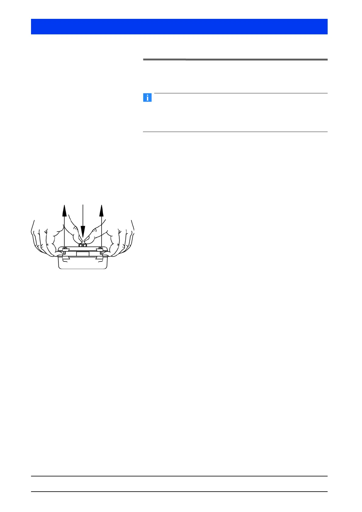
Unscrew the cover of the supplied limit-switch box and pull it
off, as shown in the illustration, while pushing down the
limit-switch shaft. Caution: Do not lose the cover sealing!
Remove shaft mounting bracket by opening the screws and
take off the limit-switch shaft.
Clamp swivel drive in vise (use soft jaws)
Apply LOCTITE (or a similar adhesive) on mounting thread, put
on the supplied cork sealing and attach the bottom part of the
limit-switch box. Fix it using the screws supplied.
The two trip cams on the limit-switch shaft are fixed by one
screw each. Untighten these screws.
Place limit-switch shaft with the Allen key onto the upper four
cornered shaft of the drive or the spring lock unit. DO NOT
HAMMER – DO NOT APPLY FORCE!
Install shaft mounting bracket again.
Adjusting the trip cams
Set revolving wings of the swivel drive to the initial position.
Caution: The mechanical end stops of the swivel drive should
have been set already to make subsequent correction of the
trip cams superfluous.
Move the respective trip cams on the guide ring until a soft click
indicates that the contact of the micro push-button (… -3U) or
micro push-button (… -4U) has switched. To be on the safe
side, move the trip cams by about 2-3 degrees further and
tighten the clamping screw.
Move revolving wings to the opposite stop position. Com-
pressed air is needed for single-acting swivel drives with spring
lock unit.
Proceed accordingly with the second trip cam.