54733BA26
1 – 32 02.2017
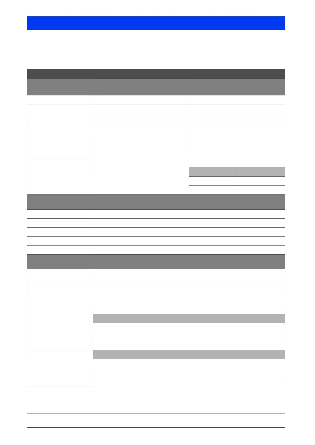
5 Explosion Protection Volume 1
5.5.5 Electrical safety characteristics of the associ-
ated equipment
Signal circuits LB 480-...-3B (Sink) LB 480-...-4B (Source)
Current output
(Terminals 17, 18)
HART
®
/ 4 ... 20mA
linear characteristic curve
max. output voltage U
a
= 25,2V
max. output current I
a
= 101mA
max. output rating P
a
= 635mW
max. input voltage U
i
= 30V
max. input current I
i
= 152mA
max. input rating P
i
= 1,14W
max. internal inductance L
i
= 20μH
max. internal capacitance C
i
= 3nF
Individual reactances
according to
EN 60079-11, Table A2,
Figure A4 / A6
IIC IIB
L
o
= 17mH L
o
= 4mH
C
o
= 0.82μF C
o
= 0.107μF
Signal output
(Terminals 11, 12)
Open collector circuit
linear characteristic curve
max. input voltage U
i
= 15V
max. input current I
i
= 26.6mA
max. input rating P
i
= 100mW
max. internal inductance negligibly small
max. internal capacitance C
i
= 11nF
Signal output
(Terminals 15, 16)
Thermometer circuit (PT100)
linear characteristic curve
max. output voltage U
o
= 14V
max. output current I
o
= 27,7mA
max. output rating P
o
= 97mW
max. internal inductance negligibly small
max. internal capacitance C
i
= 11nF
Maximum permissible exter-
nal values jointly acting
reactances (C
i
is not taken
into account)
IIB
L
o
= 0.1mH, C
o
= 4.6μF
L
o
= 0.5mH, C
o
= 4.0μF
L
o
= 1.0mH, C
o
= 3.3μF
Maximum permissible exter-
nal values jointly acting
reactances (C
i
is not taken
into account)
IIC
L
o
= 0.1mH, C
o
= 0.73μF
L
o
= 0.5mH, C
o
= 0.71μF
L
o
= 1.0mH, C
o
= 0.59μF