Operating Instructions ACU
If a digital input is configured as a PWM or repetition frequency input, this input
cannot be used for other functions.
Check the link of the digital inputs to other functions.
The signal frequency at the selected repetition frequency input can be scaled via the parameter
Divider 497. The parameter value can be compared to the number of division marks of an encoder
per rotation of the drive. The frequency limit of the parameterized digital input is to be taken into
account for the frequency of the input signal.
The reference value specification within the different functions enables the use of the
repetition frequency signal as a percentage figure. A signal frequency of 100 Hz at the
repetition frequency input corresponds to 100%, 1 Hz corresponds to 1%. The
parameter Divider 497 is to be used in a way comparable with the speed sensor
simulation.
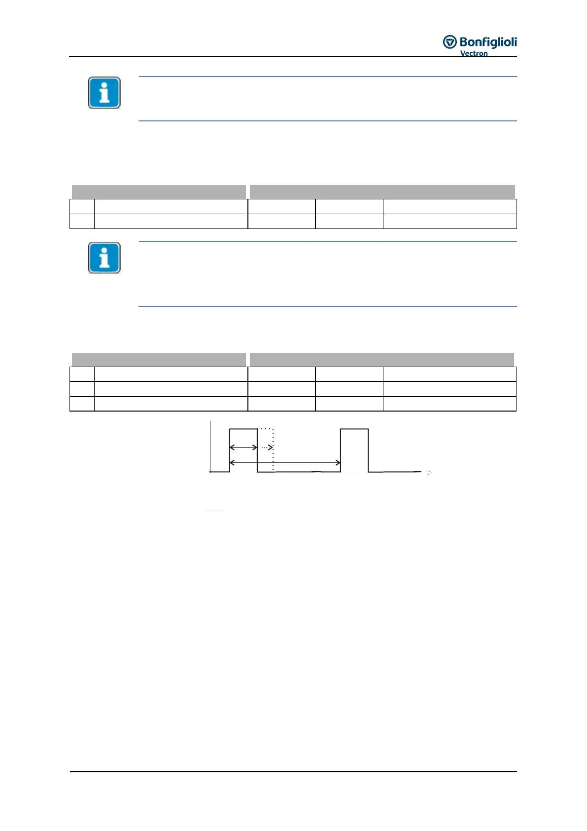
Via parameters Offset 652 and Amplification 653 the PWM input signal can be adjusted for the
application.
For definition of reference values, the following settings are possible:
For reference frequencies:
Reference Frequency Source 475 = “32 - Abs. value/PWM Inp. (F3)”. The PWM-value for
the signal is referred to Maximum Frequency 419.
For reference percentages:
Reference Percentage Source 476 = “32 - Abs. value/PWM Inp. (F3)”. The PWM-value for
the signal is referred to Maximum Reference Percentage 519.
The actual value of the PWM input is shown in parameter PWM-Input 258.
653652 % ionAmplificat
T
T
ges
on
OffsetValuePWM