19
Panel Descriptions
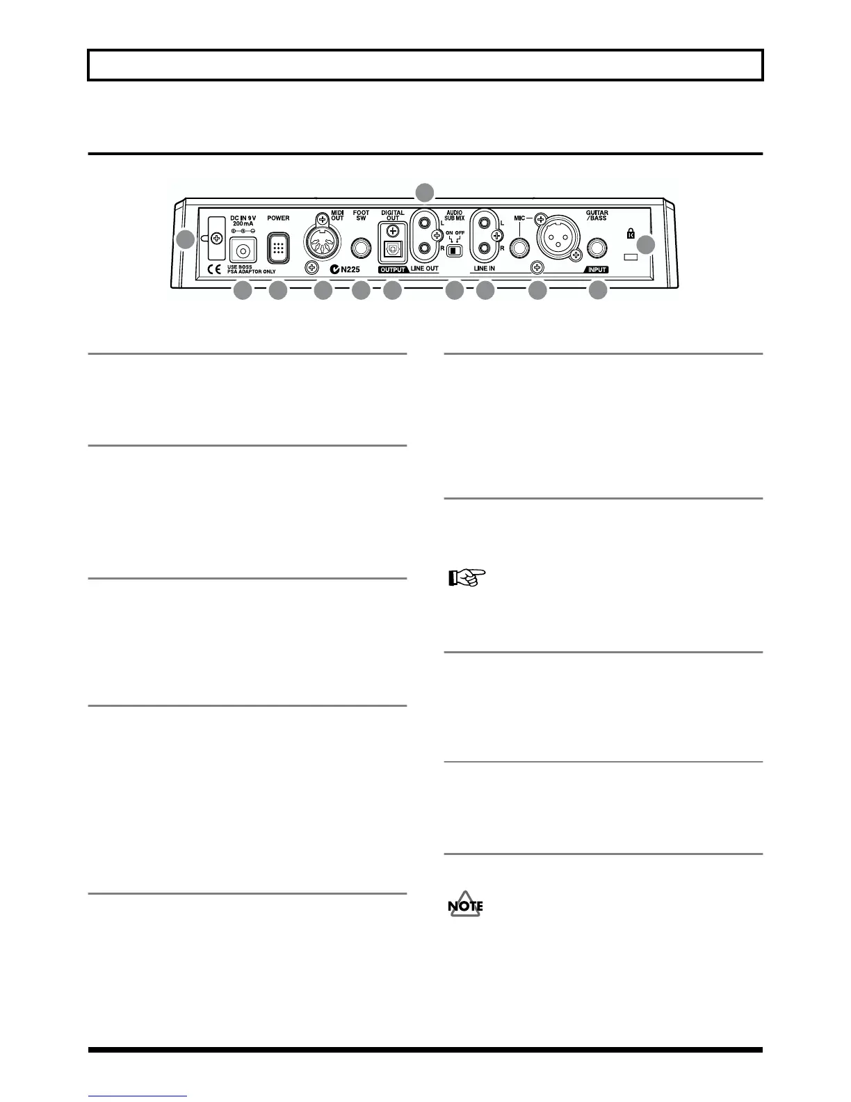
Rear Panel
fig.00-05
1 GUITAR/BASS jack
High-impedance input jack to directly connect your guitar or
bass.
2 MIC jack (TRS/XLR types)
These jacks allow a mic to be connected.Both standard TRS
jacks (p. 23) and XLR jacks are provided.
* If microphones are connected to both jacks, the TRS jack is
given priority.
3 LINE IN jack
These are input jacks for analog audio signals.These jacks are
used to connect CD players and other audio devices and
keyboards, rhythm machines, and other external sound
sources.
4 AUDIO SUB MIX switch
Turn this switch on to mix the signal input from LINE IN
with the output to LINE OUT.
With INPUT SELECT set to a setting other than LINE, and
AUDIO SUB MIX turned on, the signal is mixed and output
to LINE OUT.
* Only the analog signal is mixed, so the DIGITAL OUT signal
will not be affected.
5 LINE OUT jack
These are output jacks for the analog audio signal. You can
connect MD recorders, tape recorders, or other recording
devices to record the output analog signal from the BR-532.
6 DIGITAL OUT connector
Optical connector for outputting digital audio signals. The
same sound that is output from LINE OUT is also output
from DIGITAL OUT, so you can digitally record the output
from the BR-532 to DAT recorders, CD recorders, and other
digital recording devices.
7 FOOT SW (Foot Switch) jack
This is an input jack for connecting a separately sold foot
switch (BOSS FS-5U, Roland DP-2). By using this FOOT SW
jack, you can start/stop playback, punch in/out, and more.
In order to use a foot switch (p. 46)
8 MIDI OUT connector
Connector for sending MIDI data.Connect it to the MIDI IN
connector of an external MIDI device (rhythm machine or
sound module).
9 POWER switch
This is the power switch. It turns the power of the BR-532
on/off.
10 DC IN (AC Adaptor) jack
Connect the AC adaptor (PSA-series; optional) to this jack.
You must use only the PSA-series AC adaptor. Use of
any other adaptor may cause overheating or
malfunctions.
1
234
5
68 79
10
11
12