Confidential
5-64
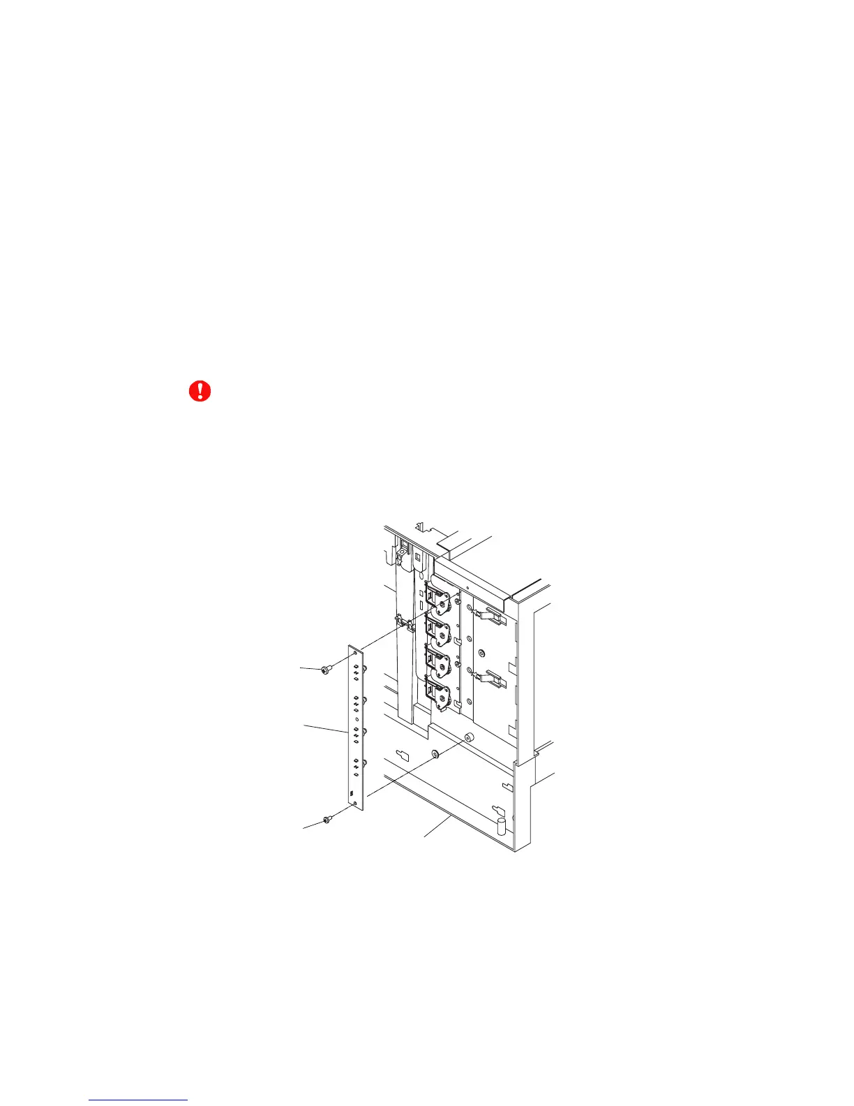
5.1.54 Toner Sensor PU (TTR)
(1) Remove the setscrew (BT3x8 and BT3x6, 1 each) of the toner sensor PU (TTR).
(2) Disconnect the connector connecting to the toner sensor PU (TTR).
(3) Remove the toner sensor PU (TTR) from the frame.
<Confirmation Items>
• Is the grounding wire securely installed to the indicated position?
• Isn't any harness caught?
• Is the appropriate screw used?
• Is each output terminal of the HV power supply PU installed properly?
• After above confirmation, confirm the safety through the withstand voltage test or with
the insulation tester.
CAUTION
Replacement of the toner sensor PU (TPD/TTR) requires the substantial disassembly and
also reassem-bly. As the inappropriate assembly procedures and the wrong use of screws
affect the product safety and the product performance, the appropriate assembly proce-dures
and the caution items must be respected. (This work requires the insulation withstand
voltage test and the measurement of the insulation resistance.)
Fig. 5-101
Toner sensor PU (TTR)
BT3
 Loading...