A112102 PD Test Checking Kit (Option)
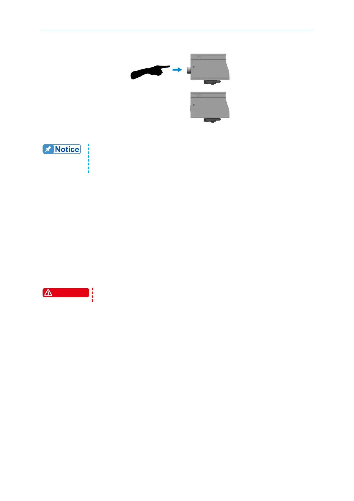
Figure 8-2 Hiding Rotary Knob Diagram
1. When the settings are done, the Voltage Trigger and PD Interval rotary
knobs can be pressed down to hide them inside the device as shown in
Figure 8-2 to reduce the chance of wrong touch.
2. Press the rotary knob again and it will return to its initial state for reset.
(5) PD Capacitance Rotary Knob
It sets the level for partial discharge. The range is OFF, #1~#7. When it is set to OFF, t
he
A
112102 will not send out partial discharge simulation signals even if the 11210 output
voltage is higher than the trigger voltage. When setting to #1~#7, the levels are from
small to large under the same test conditions; however, the level sizes of partial
discharge are varied based on different test conditions.
(
6) Status indicators: There are 3 LED lights.
POWER: When the green light is on, it means the A112102 is running normally.
DANGER: When the red light is on, it means inputting high voltage for testing. Do
not touch the voltage input terminal at this time.
PD: When the orange light blinks, it means the 11210 output voltage is higher than
t
he set triggering voltage, and the A112102 sends out partial discharge signal.
Do not touch the test terminal or the DUT when the light of testing status is
on or blinks.
(7) Partial Discharge Mode Switch
It adjusts the A112102 partial discharge signal sending out mode to Single and Multiple.
When set to Single,
On
ly one partial discharge is occurred during the entire test. If the PD level is higher
than the PD Compare set by 11210 (see section 6.4.2 PD Compare), the 11210
panel will show VPD times 1 when the test ends.
DANGER light is always on during testing while the PD light only blinks once.
W
hen set to Multiple,
The A112102 will follow the PD interval set to send out PD simulation signal
continuously, and the 11210 panel will show multiple VPD and CPD measurement
results when the test ends.
DANGER light is always on while the PD light blinks continuously.