Battery Cell Insulation Tester 11210 User’s Manual
5-16
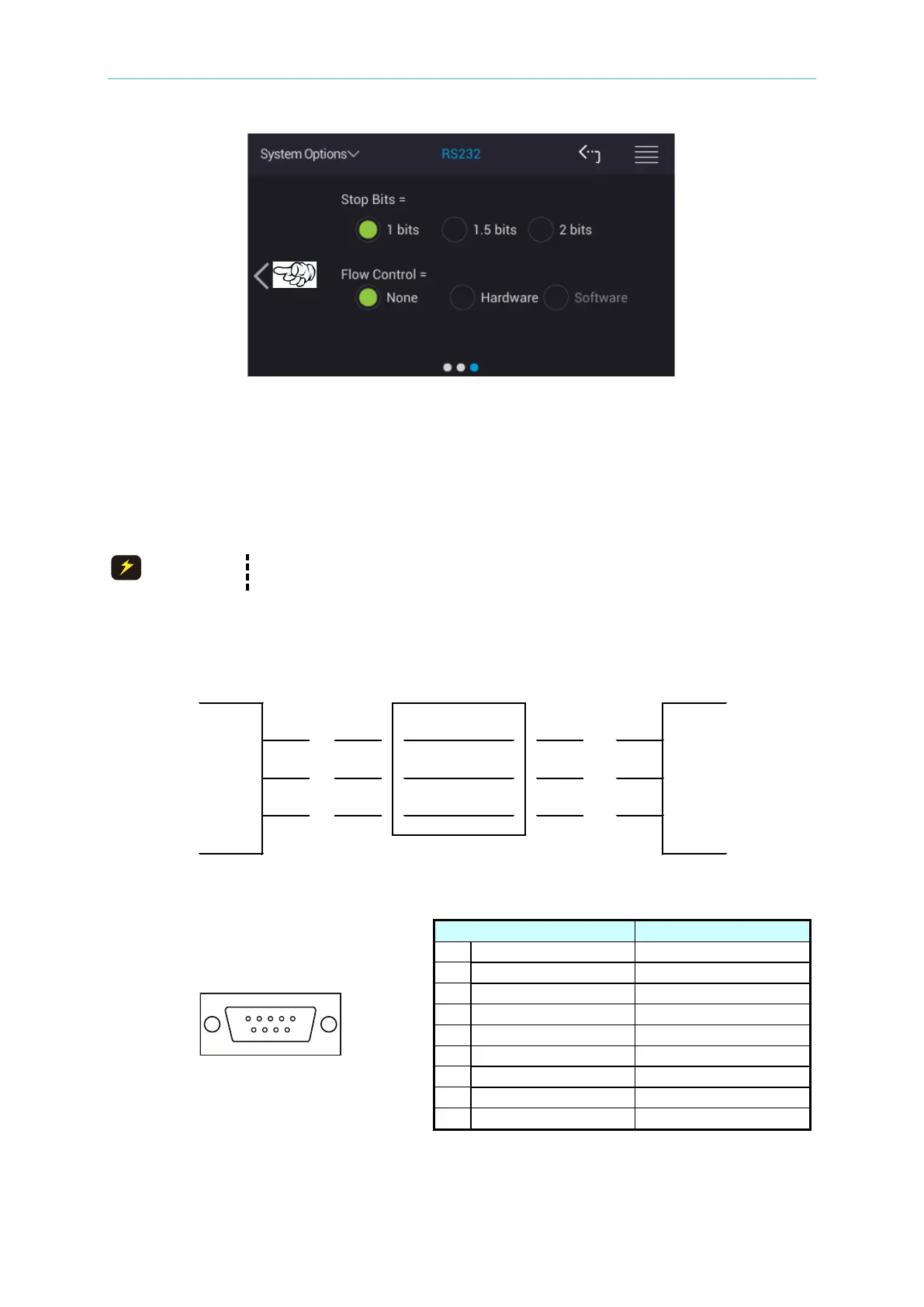
Stop Bits:
Stop bits contain three selections of 1 bit, 1.5 bits and 2 bits with factory default to 1 bit when
shipped.
Flow Control:
There are None, Hardware and Software for selection with factory default to None when
shipped.
The baud rate setting should be same as the RS-232C interface card,
otherwise there may have data transmission problem.
Connection of RS-232C signal line:
RS-232C connector of the tester is a 9-pin female connector, the table of RS-232C signal line
and pin as below shows.