7-5
Cisco CRS-1 Series Carrier Routing System Getting Started Guide
Chapter 7 RP Redundancy and Hardware Administration on Cisco IOS XR Software
Command Syntax for Hardware Nodes (location nodeID)
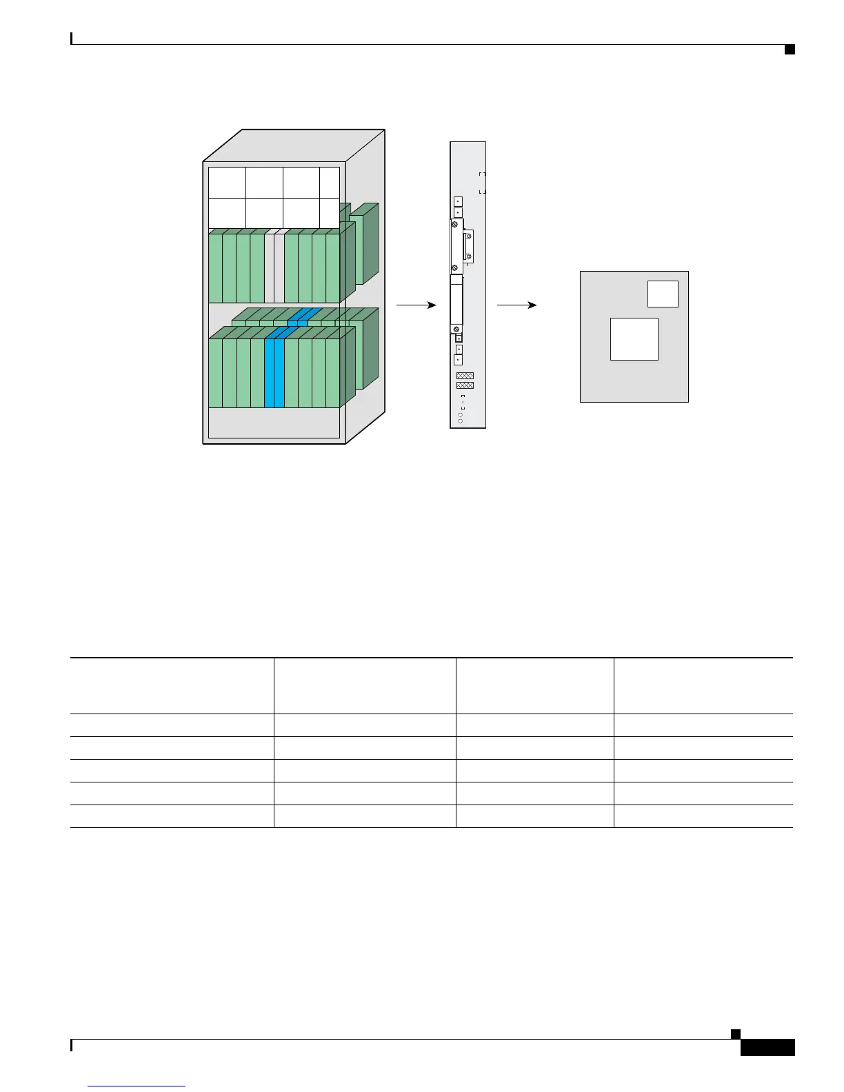
Figure 7-1 NodeID: rack/slot/module
The nodeID components are as follows:
• The rack number in a single-chassis system is always “0.”
• The slot is the physical slot number where the card is installed.
• The module is the CPU or SP on the card that executes the commands.
Table 7-2 summarizes the nodeID for each type of card in a single-chassis system:
Displaying the nodeID for Cards in the System
Enter the show platform command to display the node IDs of installed cards. The “Node” column
identifies the node ID of the card (see Figure 7-2).
CPU0
Rack=0 Slot=Physical slot
of the card
Module="CPU0" or "SP"
on the card
SP
Processors on Card
116537
PLIM
PL8
PLIM
PL9
PLIM
PL
10
PLIM
PL
11
PLIM
PL
12
PLIM
PL
13
PLIM
PL
14
PLIM
PL
15
Line cardLine card
PLIM
PL0
PLIM
PL1
PLIM
PL2
PLIM
PL3
PLIM
PL4
PLIM
PL5
PLIM
PL6
PLIM
PL7
FC0
FC1
A0
B0
A1
B1
A2
B2
AM0
AM1
RP0
RP1
Console
AUX
PC Card
(disk1:)
MGMT ETH
CNTL ETH 1
CNTL ETH 0
Primary
Status
HDD
RP
Table 7-2 Location nodeID: rack/slot/module
Card Type
(the card type that you are issuing
commands to)
Rack
(always “0” in a
single-chassis system)
Slot
(the physical slot where
the card is installed)
Module
(the entity on the card that
executes the commands)
Route processor
0
RP0 and RP1 CPU0
Line card
0
0–15 CPU0
Switch fabric module
0
SM0–SM7 SP
Alarm cards
0
AM0–AM1 SP
Fan controller cards
0
FC0–FC1 SP
 Loading...


