2-3
Cisco CRS-1 Series Carrier Routing System Getting Started Guide
Chapter 2 Cisco IOS XR Basic Configuration Management
Connecting and Communicating with the Router
Tip For additional information on configuring terminal services, including terminal servers and templates,
refer to Implementing Physical and Virtual Terminals on Cisco IOS XR Software in the Cisco IOS XR
Series System Management Configuration Guide.
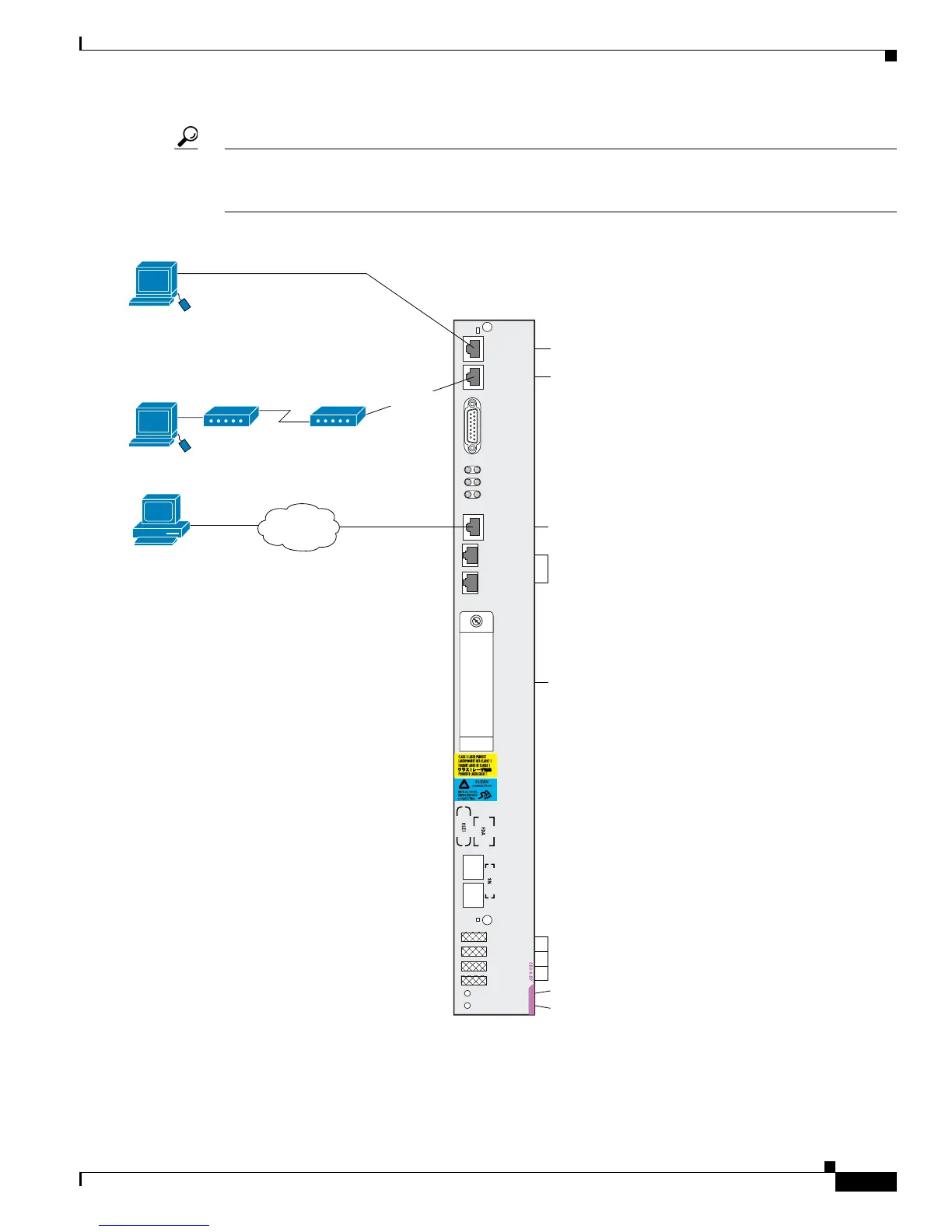
Figure 2-2 Communication Ports on the RP for a Cisco CRS-1 8-Slot Line Card Chassis
Primary
Status
Console
AUX
CRITICAL
MAJOR
MINOR
122803
Optical GigE for control plane:
not user-configurable
Terminal connection
Modem connection
Primary RP (On=Primary)
Card status (Green=OK)
User-removable flash disk1:
stores installation PIE files.
A second internal Flash disk0:
stores installed software and
active configurations.
Management Ethernet connection
for out-of-band network communication
LED status
displays
(alphanumeric)
ALARM
PID/VID
MGMT
ETH
CNTL
ETH 0
PC
CARD
CNTL
ETH 1
EXT
CLK 1
EXT
CLK 2
Remote terminal for
CLI communication.
RJ-45 cable
Local terminal or
terminal server for
CLI communication.
RJ-45 cable
Remote CLI, CWI, XML,
or SNMP communication.
Remote file storage.
Ethernet cable
Network
 Loading...


