15-7
Cisco ME 3400 Ethernet Access Switch Software Configuration Guide
OL-9639-07
Chapter 15 Configuring MSTP
Understanding MSTP
Port Role Naming Change
The boundary role is no longer in the final MST standard, but this boundary concept is maintained in
Cisco’s implementation. However, an MST instance port at a boundary of the region might not follow
the state of the corresponding CIST port. Two cases exist now:
• The boundary port is the root port of the CIST regional root—When the CIST instance port is
proposed and is in sync, it can send back an agreement and move to the forwarding state only after
all the corresponding MSTI ports are in sync (and thus forwarding). The MSTI ports now have a
special master role.
• The boundary port is not the root port of the CIST regional root—The MSTI ports follow the state
and role of the CIST port. The standard provides less information, and it might be difficult to
understand why an MSTI port can be alternately blocking when it receives no BPDUs (MRecords).
In this case, although the boundary role no longer exists, the show commands identify a port as
boundary in the type column of the output.
Interoperation Between Legacy and Standard Switches
Because automatic detection of prestandard switches can fail, you can use an interface configuration
command to identify prestandard ports. A region cannot be formed between a standard and a prestandard
switch, but they can interoperate by using the CIST. Only the capability of load balancing over different
instances is lost in that particular case. The CLI displays different flags depending on the port
configuration when a port receives prestandard BPDUs. A syslog message also appears the first time a
switch receives a prestandard BPDU on a port that has not been configured for prestandard BPDU
transmission.
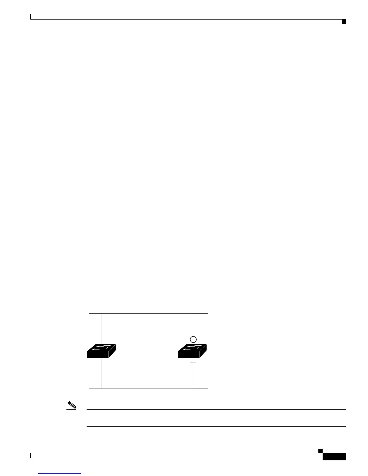
Figure 15-2 illustrates this scenario. Assume that A is a standard switch and B a prestandard switch, both
configured to be in the same region. A is the root switch for the CIST, and thus B has a root port (BX)
on segment X and an alternate port (BY) on segment Y. If segment Y flaps, and the port on BY becomes
the alternate before sending out a single prestandard BPDU, AY cannot detect that a prestandard switch
is connected to Y and continues to send standard BPDUs. The port BY is thus fixed in a boundary, and
no load balancing is possible between A and B. The same problem exists on segment X, but B might
transmit topology changes.
Figure 15-2 Standard and Prestandard Switch Interoperation
Note We recommend that you minimize the interaction between standard and prestandard MST
implementations.
Segment X
MST
Region
Segment Y
92721
Switch A
Switch B