GR740-UM-DS, Nov 2017, Version 1.7 106 www.cobham.com/gaisler
GR740
sets the DATAMUX field to a value between 1-4 to replace a quarter of the data bus, or to 5 to replace
the active checkbit half. When writing, the selected part will also be written into the top bits, and
when reading the top bits will be copied over into the selected part.
10.5.8 Memory fault recovery
The above features are designed to make the system capable to deal with a permanent fault in an
external memory chip.
A basic sequence of events is as follows:
1. The system is running correctly with EDAC enabled and the larger code A is used.
2. A memory chip gets a fault making the SDRAM deliver incorrect data on one byte lane. The
memory controller keeps delivering error-free data but reports a correctable error on every read
access.
3. A logging device (the memory scrubber) registers the high frequency of correctable errors and
signals an interrupt.
4. The CPU performs a probe using the FT diagnostic registers to confirm that the error is perma-
nent and on which physical lane the error is.
5. After determining that a permanent fault has occurred, the CPU reconfigures the memory con-
troller as follows (all configuration register fields changed with a single register write):
The data multiplexing control field is set so the top checkbit half replaces the failed part of the
data bus.
The code boundary register is set to the lowest memory address.
The boundary address enable and boundary address update enable bits are set.
The mask correctable error bit is set
6. The memory data and checkbits are now regenerated using locked read-write cycles to use the
smaller code and replace the broken data with the upper half of the checkbit bus. This can be done in
hardware using the memory scrubber.
7. After the whole memory has been regenerated, the CPU disables the code boundary, changes the
code selection field to code B, and unsets the mask correctable error bit.
After this sequence, the system is now again fully operational, but running with the smaller code and
replacement chip and can again recover from any single-nibble error. Note that during this sequence,
it is possible for the system to operate and other masters can both read and write to memory while the
regeneration is ongoing.
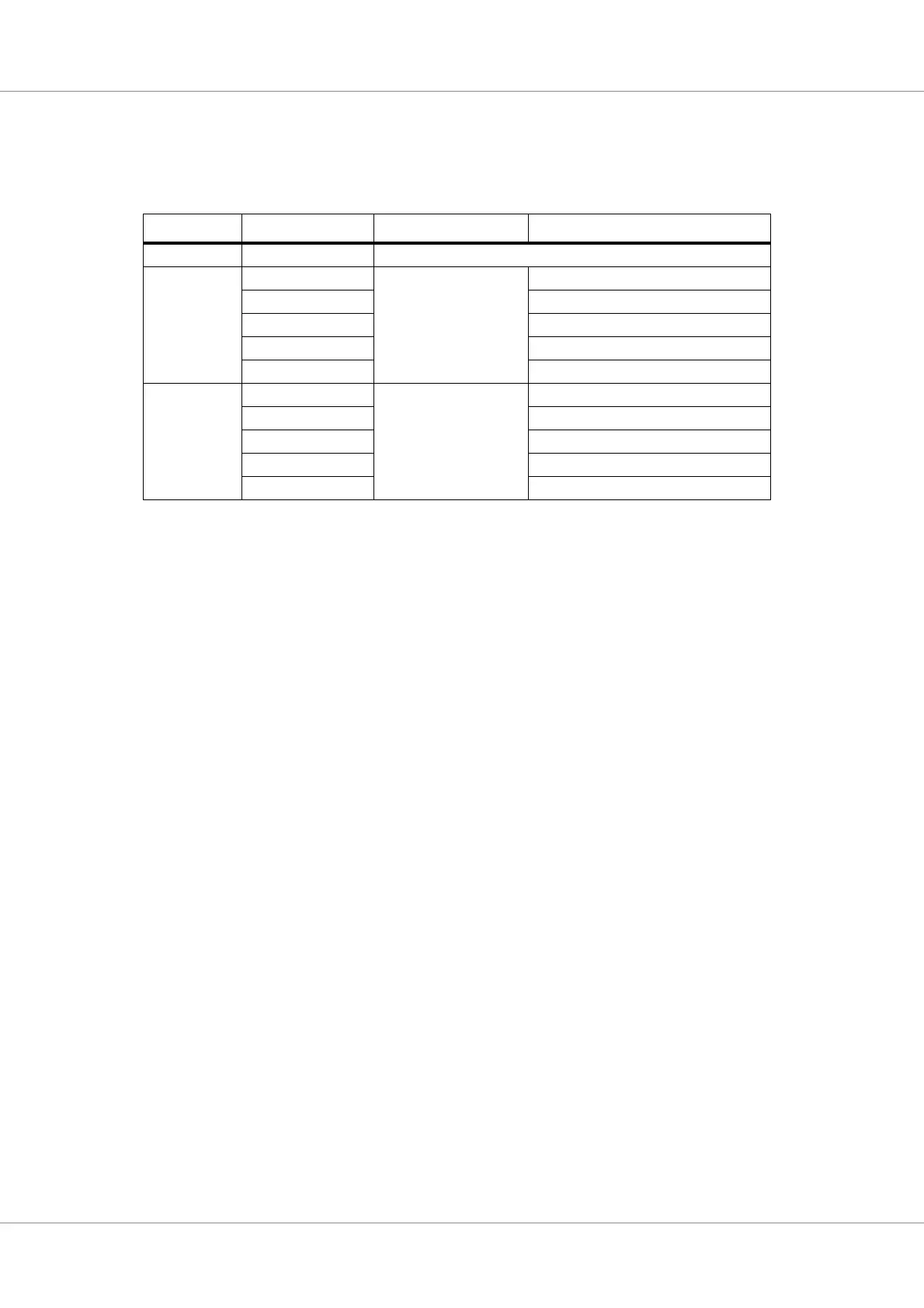
Table 93. DATAMUX configurations
mem_ifwidth DATAMUX Top bits swapped in Replaced "faulty" slice
- 0 No swapping
0 1 mem_dq(95:80) mem_dq(15:0)
2 mem_dq(31:16)
3 mem_dq(47:32)
4 mem_dq(63:48)
5 mem_dq(79:64)
1 1 mem_dq(79:72) mem_dq(7:0)
2 mem_dq(15:8)
3 mem_dq(23:16)
4 mem_dq(31:24)
5 mem_dq(71:64)