GR740-UM-DS, Nov 2017, Version 1.7 230 www.cobham.com/gaisler
GR740
15.6.1 DMA channel
The first level is a linked list of DMA channel descriptors. Each descriptor has a pointer to its data
descriptor list and a pointer to the next DMA channel. The last DMA channel descriptor should
always point to the first DMA channel for the list to be a closed loop. The descriptor needs to be
aligned to 4 words (0x10) in memory and have the following structure:
The number of enabled DMA channels must be stored in the “Number of DMA channels“ field in the
DMA control register accessible via the APB slave interface.
15.6.2 Data descriptor
The second descriptor level is a linked list of data transfers. The last descriptor in this list needs to be
a disabled descriptor. To add a new data transfer, this disabled descriptor is updated to reflect the data
transfer and to point to a new disabled descriptor. The control word in the descriptor should be
updated last to enable the valid descriptor. To make sure the DMA engine reads this new descriptor,
the enable bit in the DMA control register should be updated. The descriptor needs to be aligned to 4
words (0x10) in memory and have the following structure:
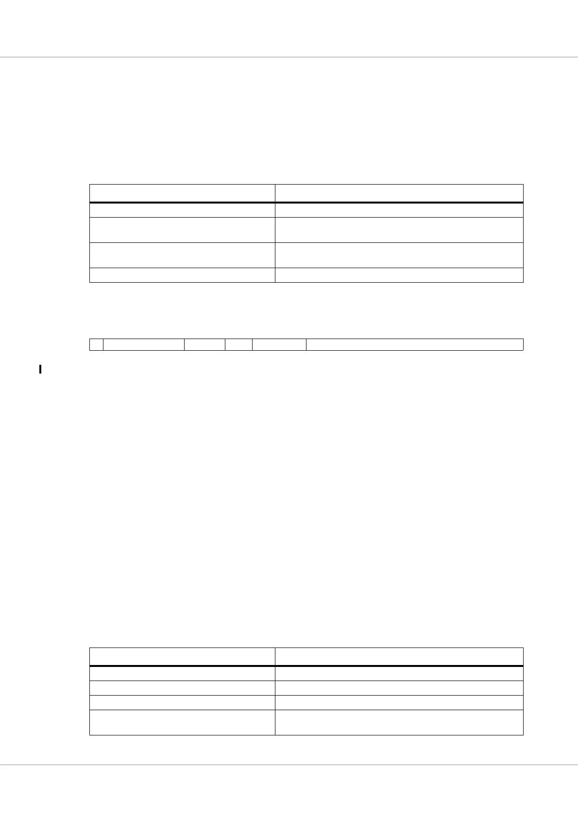
Table 266.GRPCI2: DMA channel descriptor structure
Descriptor address offset Descriptor word
0x00 DMA channel control
0x04 Next DMA channel (32-bit address to next DMA channel descrip-
tor).
0x08 Next data descriptor in this DMA channel (32-bit address to next
data descriptor).
0x0C RESERVED
Table 267. GRPCI2 DMA channel control
31 30 25 24 22 21 20 19 16 15 0
EN RESERVED CID Type RESERVED Data descriptor count
31 Channel descriptor enable. This bit must be set to 1 in GR740 silicon revision 0.
30: 25 RESERVED
24: 22 Channel ID. Each DMA channel needs a ID to determine the source of a DMA interrupt.
21: 20 Descriptor type. 01 = DMA channel descriptor.
19: 16 RESERVED
15: 0 Maximum number of data descriptors to be executed before moving to the next DMA channel. 0
indicates that all data descriptors should be executed before moving to the next DMA channel.
Table 268.GRPCI2: DMA data descriptor structure
Descriptor address offset Descriptor word
0x00 DMA data control
0x04 32-bit PCI start address
0x08 32-bit AHB start address
0x0C Next data descriptor in this DMA channel (32-bit address to next
data descriptor).