GR740-UM-DS, Nov 2017, Version 1.7 73 www.cobham.com/gaisler
GR740
6.10.5 ASR24-31, Hardware watchpoint/breakpoint registers
Each breakpoint consists of a pair of ancillary state registers (%asr24/25, %asr26/27, %asr28/29 and
%asr30/31) registers; one with the break address and one with a mask:
Note: Setting IF=DL=DS=0 disables the breakpoint
When there is a hardware watchpoint match and DL or DS is set then trap 0x0B will be generated.
Hardware watchpoints can be used with or without the LEON4 debug support unit (DSU) enabled.
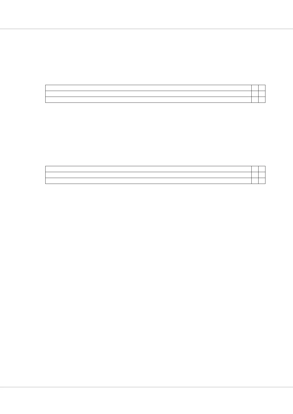
Table 53. %asr24, %asr26, %asr28, %asr30 - Watchpoint address register(s)
31 210
WADDR[31:2] R IF
NR 0 0
rw r rw
31: 2 Watchpoint address (WADDR) - Address to compare against
1RESERVED
0 Break on instruction fetch (IF) - Break on instruction fetch from the specified address/mask combi-
nation
Table 54. %asr25, %asr27, %asr29, %asr31 - Watchpoint mask register(s)
31 210
WMASKR[31:2] DL DS
NR 0 0
rw rw rw
31: 2 Watchpoint mask (WMASK) - Bit mask controlling which bits to check (1) or ignore (0) for match
1 Break on data load (DL) - Break on data load from the specified address/mask combination
0 Break on data store (DS) - Break on data store to the specified address/mask comination