GR740-UM-DS, Nov 2017, Version 1.7 87 www.cobham.com/gaisler
GR740
write policy is controlled via the cache control register. More fine-grained control can also be
obtained by enabling the MTRR registers (see text below).
9.2.3 Memory type range registers
The memory type range registers (MTRR) are used to control the cache operation with respect to the
address. Each MTRR can define an area in memory to be uncached, write-through or write-protected.
Each MTRR register consist of a 14-bit address field, a 14-bit mask and two 2-bit control fields. The
address field is compared to the 14 most significant bits of the cache address, masked by the mask
field. If the unmasked bits are equal to the address, an MTRR hit is declared. The cache operation is
then performed according to the control fields (see register descriptions). If no hit is declared or if the
MTRR is disabled, cache operation takes place according to the cache control register. The number of
implemented MTRRs is sixteen. When changing the value of any MTRR register, the cache must be
disabled and flushed (this can be done by setting the Cache disable bit when issuing a flush all com-
mand).
Note that the write-protection provided via the MTRR registers is enforced even if the cache is dis-
abled.
9.2.4 Cachability
The cache considers the address range 0x00000000 - 0x7FFFFFFF to be cachable. The cache can also
be configured to use the HPROT signal to override the default cachable area. An access can only be
redefined as non-cachable by the HPROT signal. See table 65 for information on how HPROT can
change the access cachability within a cachable address area. The AMBA AHB signal HPROT[3]
defines the access cacheable when active high and the AMBA AHB signal HPROT[2] defines the
access as bufferable when active high.
* When the HPROT-Read-Hit-Bypass bit is set in the cache control register this will generate a Mem-
ory access.
9.2.5 Cache tag entry
Table 66 shows the different fields of the cache tag entry for a cache with a way size of 512 KiB.
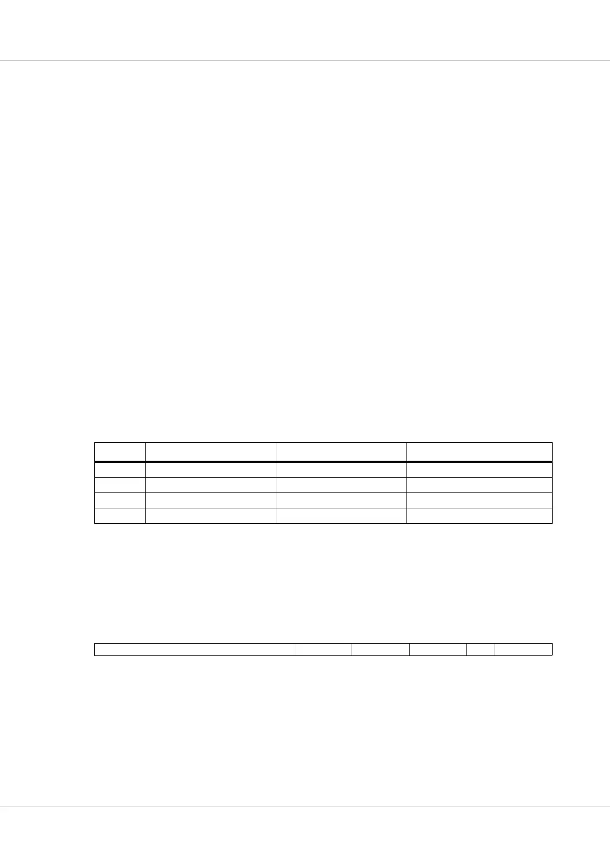
Table 65. Access cachability using HPROT.
HPROT: non-cachable, non-bufferable non-cachable, bufferable cacheable
Read hit Cache access* Cache access Cache access
Read miss Memory access Memory access Cache allocation and Memory access
Write hit Cache and Memory access Cache access Cache access
Write miss Memory access Memory access Cache allocation
Table 66. L2C Cache tag entry
31 1918109876540
TAG 000000 Valid Dirty RES LRU
31 : 19 Address Tag (TAG) - Contains the address of the data held in the cache line.
9 : 8 Valid bits. When set, the corresponding sub-block of the cache line contains valid data. Valid bit 0
corresponds to the lower 16 bytes sub-block (with offset 1) in the cache line and valid bit 1 corre-
sponds to the upper 16 bytes sub-block (with offset 0) in the cache line.
7 : 6 Dirty bits When set, this sub-block contains modified data.
5RESERVED
4 : 0 LRU bits