Home
Comtech EF Data
Switch
CRS-300
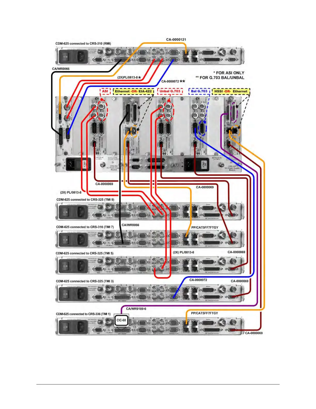
Page 102 (Figure 4-10. CRS-300 to CDM-625;A Cable Connection Example - G.703-Driven Configuration)
Comtech EF Data CRS-300 - Figure 4-10. CRS-300 to CDM-625;A Cable Connection Example - G.703-Driven Configuration
298 pages
Manual
Save Page as PDF
To Next Page
To Next Page
To Previous Page
To Previous Page
Loading...
CRS
-
300 1:10 Red
undancy S
witch
MN/CRS300.I
OM
Cables an
d Connect
ions
Revision 19
4–
30
Figure
4-
10
.
CRS
-
300 to CDM
-
625/
A
Cable Connect
ion Example
–
G.703
-
driven
Configuration
(Connections
shown for RMI and TMIs 1, 3
, 5, 7, and 9 only)
101
103
Table of Contents
Main Page
Default Chapter
3
Table of Contents
3
Tables
11
Figures
12
Preface
17
About this Manual
17
Related Documents
17
Conventions and References
18
Patents and Trademarks
18
Warnings, Cautions and Notes
18
Examples of Multi-Hazard Notices
18
Recommended Standard Designations
19
Safety and Compliance
19
Electrical Safety and Compliance
19
Electrical Installation
19
Operating Environment
19
European Union Radio Equipment and Telecommunications Terminal Equipment (R&TTE) Directive (1999/5/EC) and en 301 489-1
20
European Union Electromagnetic Compatibility (EMC) Directive (2004/108/EC)
20
European Union Low Voltage Directive (LVD) (2006/95/EC)
21
European Union Rohs Directive (2002/95/EC)
21
European Union Telecommunications Terminal Equipment Directive (91/263/EEC)
21
CE Mark
21
Product Support
21
Comtech EF Data Headquarters
22
Warranty Policy
22
Limitations of Warranty
22
Exclusive Remedies
23
Chapter 1. Introduction
25
Overview
25
System-Level Block Diagram
28
Figure 1-1. Typical Redundancy System-Level Block Diagram
28
CRS-280/280L Functional Schematic
29
Figure 1-2. CRS-280/280L if Switch Functional Schematic
29
Compatibility
30
Table 1-1. CRS-300 Compatibility Table
30
Description of CRS-300 Features
31
Front Panel
31
Figure 1-3. CRS-300 Front Panel Features
31
Rear Panel
32
Figure 1-4. CRS-300 Rear Panel - Configuration Example
32
Plug-In Module (Card) Assemblies
33
System Controller Card Assembly
33
Power Supply Card Assemblies
33
Modem Interface Cards
34
CDM-625/A, CDM-570/A, CDM-570L/AL, CDM-600/L Interface Cards
34
Figure 1-12. CRS-365D TMI E1 (1-4 Ports) (PL/12985-2)
35
Figure 1-8. CRS-310 RMI (PL/9579-1)
35
Figure 1-9. CRS-320 TMI EIA-232/-422 (PL/9581-1)
35
RMI Card
35
TMI Cards
35
Cards
36
SLM-5650/5650A, CDM-Qx/Qxl, CDM-710G/710GL, CDM-710, CDM-700 Interface Cards
36
Figure 1-14. CRS-305 RMI (PL/11494-1)
37
Figure 1-15. CRS-306 RMI (PL/11494-2)
37
Figure 1-16. CRS-307 RMI (PL/11494-3)
37
RMI Cards
37
Figure 1-17. CRS-315 TMI
38
Figure 1-18. CRS-316 TMI RS422
38
Figure 1-19. CRS-325 TMI
38
Figure 1-21. CRS-336 TMI HSSI or Gige (PL/12499-1)
38
TMI Cards
38
Optional CRS-350 ESC Switch
39
Figure 1-22. CRS-345 TMI G.703 (4 Ports) (PL/11495-1)
39
Figure 1-23. CRS-365 TMI E1 (1-4 Ports) (PL/12985-1)
39
Figure 1-24. CRS-350 ESC Switch - Front Panel
39
Figure 1-25. CRS-355 UDI
40
Figure 1-26. CRS-350 ESC Switch - Rear Panel
40
Summary of Specifications
41
1:10 Redundancy Switch Specifications
41
Modem Vs. Terrestrial User Data Interface Specifications
42
And CRS-280L if Switch Specifications
43
ESC Switch Specifications
43
Dimensional Envelope Details
44
Figure 1-27. CRS-300 1:1 Redundancy Switch
44
Figure 1-28. CRS-280 (70/140 Mhz) if Switch
45
Figure 1-29. CRS-280L (L-Band) if Switch
46
Figure 1-30. CRS-350 ESC Switch
47
Chapter 2. Installation
49
Unpack and Inspect the Shipment
49
Figure 2-1. Unpacking and Inspecting the Shipment
49
Install the Unit into a Rack Enclosure
50
Figure 2-2. Typical Rack Mounting Configuration
52
Cabling Connection Types
53
Coaxial Cable Connections
53
Figure 3-1. Coaxial Connector Examples
53
Type 'BNC
54
Type 'F
54
Type 'N
54
Type 'TNC
54
Chapter 3. Switch Connectors and Pinouts
54
Type 'SMA' (Subminiature Version 'A')
55
D-Subminiature Cable Connections
55
Cable Connections
55
Figure 3-2. D-Subminiature Connector Examples
55
User Data Connectors
56
Controller Connectors
56
IF Switch Control Connector, DB-25M
56
Pass-Through Connector, DB-9F
56
Table 3-1. 485 Pass-Through User Data Connector
56
Remote Control Connector, DB-9M
57
Table 3-2. Remote Control Connector
57
System Alarms Connector, DB-25F
58
Table 3-3. System Alarms Connector
58
TMI User Data Connectors
59
EIA-232/422/V.35 Connector, DB-25F (CRS-316)
59
Table 3-4. EIA-232/422/V.35 Connector
59
EIA-232/422/V.35/LVDS Connector, DB-25F (CRS-320/340)
60
Table 3-5. EIA-232/422/V.35/LVDS Connector
60
ASI Connectors, BNC (CRS-325)
61
Khz IDR Connector, RJ-45F (CRS-330)
61
Table 3-6. ASI Connectors
61
Table 3-7. 8 Khz - IDR ESC Connector
61
Balanced G.703 Connector, DB-15F (CRS-325/330/340)
62
Table 3-8. Balanced G.703 Connector
62
Unbalanced G.703 Connectors, BNC (CRS-325/330/340)
63
Unbalanced G.703 4-Port Connectors, BNC (CRS-345)
63
Table 3-9. Unbalanced G.703 Connectors
63
Table 3-10. Unbalanced G.703 Connectors
63
HSSI Connector, HD-50F (CRS-336/370)
64
Table 3-11. HSSI Connector
64
10/100/1000 Gigabit Ethernet Connector, RJ-45F (CRS-316/336)
65
Table 3-12. 10/100/1000 Gigabit Ethernet Connector Pinouts
65
Quad E1 Connectors, RJ-48F (CRS-365)
66
Table 3-13. Quad E1 Connector Pinouts (Typical Ports 1 through 4)
66
Quad E1 Connectors, DB-9F (CRS-365D)
67
Table 3-14. Quad E1 Connector Pair Pinouts
67
Chassis Ground and Power Connections
68
Figure 3-3. CRS-300 Chassis Ground Interfaces
68
Figure 3-4. CRS-300 Chassis Power Supply Interfaces
69
Figure 3-5. Chassis AC Power Interface (CRS-240 Power Supply Module)
69
Figure 3-6. Apply AC Power
70
Figure 3-7. Replace the AC Fuses
70
Direct Current (DC) Power Interface
71
Figure 3-8. Chassis DC Power Interface (CRS-250 DC Power Supply Module)
71
Figure 3-9. Apply DC Power
71
Chapter 4. Cables and Connections
73
Overview
73
Switch-To-Switch Connections
75
To CRS-280/280L Connection
75
To CRS-350 Connection
75
To CRS-350 and CRS-280/280L Connection
76
Figure 4-1. Control Cable Connection Example for CRS-300 to CRS-280
77
Figure 4-2. Control Cable Connection Example for CRS-300 to CRS-280L
78
Figure 4-3. Control Cable Connection Example for CRS-300 to CRS-350
79
Figure 4-4. Control Cable Connection Example for CRS-300 to CRS-350 to CRS-280
80
Figure 4-5. Control Cable Connection Example for CRS-300 to CRS-350 to CRS-280L
81
IF Cable Connections
83
IF Cable Connections - Single Transponder (Without CRS-280/280L)
84
Figure 4-6. if Cabling Example – Single Transponder Configuration
85
IF Cable Connections - Multiple Transponder (Using if Switch)
86
Figure 4-7. if Cabling Example – Multiple Transponder Configuration
87
CDM-625/A Modem Connections
89
RMI/TMI Limitations and Considerations
89
Carrier-In-Carrier ® (Cnc) Data Connections
91
Figure 4-8. CDM-625/A to CDM-625/A Cnc ® Cable Connection Example
92
Control and Data Connections - CRS-300 to Modem
93
Control Cabling Requirement (Regardless of Driving Traffic Data Type)
93
Table 4-1. CDM-625/A Cable Usage (RMI/TMI)
93
Balanced / Unbalanced Data Connections
94
Quad E1 Data Connections
95
ASI Data Connections
96
Data Connections
97
HSSI Data Connections
98
LVDS Data Connections
98
Ethernet Data Connections
98
Ethernet Data Connection - Wired-Thru Method (no Sub-Mux)
99
Ethernet Data Connection - Wired-Around Method (Sub-Mux)
100
Figure 4-9. CRS-300 to CDM-625/A Cable Connection Example – G.703-Driven Configuration
101
Figure 4-10. CRS-300 to CDM-625/A Cable Connection Example – G.703-Driven Configuration
102
Figure 4-11. CRS-300 to CDM-625/A Cable Connection Example – Quad E1-Driven Configuration
103
Figure 4-12. CRS-300 to CDM-625/A Cable Connection Example – Sub-Mux Tmis 3 & 9
104
Data Connections - CRS-300 to User
105
Data Connections - CRS-350 Engineering Service Channel (ESC) Switch
105
ESC Data Connections - Modems to CRS-350
105
ESC Data Connections - CRS-350 to User
105
Operation of the CDM-625/A in CDM-600/L Emulation Mode
105
Preparing the CDM-625/A for Operation in CDM-600/L Emulation Mode
106
Control and Data Connections - CRS-300 to Modems in CDM-600/L Emulation Mode
106
Figure 4-14. Data Cables – CRS-300 to CDM-625/A (CDM-600/L Emulation Mode)
108
CDM-570/A, CDM-570L/AL Modem Connections
109
Control and Data Connections - CRS-300 to Modems
110
User Data Connections - CRS-300 to User
110
Figure 4-15. Data Cable Connection Example – CRS-300 to CDM-570/A or CDM-570L/AL
111
SLM-5650/5650A Modem Connections
113
RMI/TMI Limitations and Considerations
114
Control Cable Connections - CRS-300 to Modems
114
Traffic Data Connections - CRS-300 to Modems
115
Ethernet Traffic Data Connections
116
Ethernet Bridge Mode Via the Optional Gbe Interface
116
Ethernet Bridge Mode Via the Optional NP Interface
116
User Data Connections - CRS-300 to User
116
ESC Data Connections - Modems to CRS-350
116
User ESC Data Connections - CRS-350 to User
117
Figure 4-16. Control and Data Cables Example #1 – CRS-300 to SLM-5650/5650A
118
Figure 4-17. Control and Data Cables Example #2 – CRS-300 to SLM-5650/5650A
119
Figure 4-18. Control and Data Cables Example #3 – CRS-300 to SLM-5650/5650A
120
CDM-Qx/Qxl Modem Connections
123
RMI/TMI Limitations and Considerations
123
Connections - CRS-300 to Modems
123
Figure 4-20. EIA-485 Multi-Drop Cabling Example – CRS-300 to CDM-Qx/Qxl
125
Control Y-Cable Connections - CRS-300 to Modems
126
Traffic Data Connections - CRS-300 to Modems
126
User Data Connections - CRS-300 to User
127
Figure 4-24. Control Cables and HSSI Data Cables – CRS-300 to CDM-Qx/Qxl
131
Figure 4-25. Control Cables and Quad E1 Data Cables – CRS-300 to CDM-Qx/Qxl
132
CDM-710G/710GL Modem Connections
133
RMI/TMI Limitations and Considerations
133
Interface Combinations
133
Control Cable Connections - CRS-300 to Modems
133
Serial Traffic Data Connections - CRS-300 to Modems
133
Ethernet Traffic Data Connections - CRS-300 to Modems
133
User Data Connections - CRS-300 to User
133
CDM-710G/710GL Modem Connections
134
Interface Combinations
134
Table 4-2. CDM-710G/710GL Interface Card Combinations
134
Control Cable Connections - CRS-300 to Modems
135
Serial Traffic Data Connections - CRS-300 to Modems
135
User Data Connections – CRS-300 to User
136
Figure 4-27. Control and Data Cables Example #2 – CRS-300 to CDM-710G/710GL
137
Table 4-3. CDM-710 Interface Card Combinations
140
CDM-710 Modem Connections
140
Ethernet Traffic Data Connections - CRS-300 to Modems
141
Control Cable Connections – CRS-300 to Modems
141
User Data Connections – CRS-300 to User
142
Figure 4-29. Control and Data Cables Example #2 – CRS-300 to CDM-710
143
Table 4-4. CDM-700 Interface Card Combinations
146
CDM-700 Modem Connections
146
Control Cable Connections – CRS-300 to Modems
147
Wired-Around Connections
148
Wired-Thru Connections
148
User Data Connections - CRS-300 to User
149
Figure 4-30. Control and Traffic Data Cables Example #1 – CRS-300 to CDM-700
150
Figure 4-31. Control and Traffic Data Cables Example #2 – CRS-300 to CDM-700
151
Figure 4-32. CDM-700 IP Connections – Wired-Thru Example #1
152
Figure 4-33. CDM-700 IP Connections – Wired-Thru Example #2
153
Figure 4-34. CDM-700 IP Connections – Wired-Around Example #1
154
Figure 4-35. CDM-700 IP Connections – Wired-Around Example #2
155
CDM-600/L Modem Connections
157
Control and Data Connections - CRS-300 to Modems
157
Figure 4-36. Data Cable Connection Example – CRS-300 to CDM-600/L
159
User Data Connections - CRS-300 to User
160
ESC Data Connections - Modems to CRS-350
160
User ESC Data Connections - CRS-350 to User
160
Chapter 5. Modem, Rmi/Tmi, and Switch Configuration
164
Configure Your Modems
164
Connect Your Modem Power
164
Modem Firmware and Hardware Requirements
164
Update Your Modem Firmware
165
Configure Your Modem Operation
165
Configure Your Modems for 1:N Redundancy
165
Configure Switch-To-CDM-625/A 1:N Redundancy
165
Configure CDM-625/A 1:N Redundancy for Carrier-In-Carrier
166
Configure Switch-To-CDM-570/A, CDM-570L/AL, CDM-600/L 1:N Redundancy
167
Configure Switch-To-SLM-5650/5650A 1:N Redundancy
167
Configure Switch-To-CDM-Qx/Qxl 1:N Redundancy
169
Figure 5-2. CDM-Qx/Qxl / CRS-300 EIA-485 Scheme
171
Configure Switch-To-CDM-710G/710GL, CDM-710, CDM-700 1:N Redundancy
172
RMI Card Configuration Reference
173
Table 5-1. RMI "JMP1" Jumper Settings (as Shipped)
173
TMI Card Configuration Reference
174
Interfaces Via the CRS-316 TMI
174
Table 5-2. CRS-316 "JP1" Jumper Settings
175
Table 5-3. CRS-316 "JP2" Jumper Settings
176
Table 5-4. CRS-316 "JP3" through "JP6" Jumper Settings
176
EIA-232/-422, V.35 Interfaces Via the CRS-320 and CRS-340 Tmis
177
Table 5-5. CRS-320/CRS-340 Jumper Settings
178
HSSI Interfaces Via the CRS-336 TMI
179
Table 5-6. CRS-336 Jumper "JP1" Settings
180
Table 5-7. CRS-336 Jumper "JP2" Settings
180
HSSI Interface Via the CRS-370 TMI
181
Table 5-8. CRS-370 Jumper "J2" Settings
181
Configure the CRS-300 Switch
182
Connect the Switch Power
182
About the Switch Fuses
182
Update the CRS-300 Switch Firmware
183
About Firmware Files, Naming, Versions, and Archive Formats
183
Switch Firmware Update Procedure
184
Getting Started: Prepare for the Firmware Download
184
Download and Extract the Firmware Update
185
Execute the CCCFLASH Upload Utility Application
187
Configure the CRS-300 Switch Operation
187
Activate the Traffic Modems
187
Verify each Active Modem Connection
188
Set the Switch Operation Mode
189
Set the Holdoff Period
189
Set the Backup Holdoff Period
190
Set the Restore Holdoff Period
190
Set the Alarm Masks
191
Chapter 6. Front Panel Operation
193
Overview
193
Front Panel LED Indicators
194
Switch Status LED Indicators
194
Modem Status LED Indicators
195
Front Panel Keypad
196
Front Panel Vacuum Fluorescent Display (VFD)
197
Opening Screen
197
Menu Structure
198
Front Panel Operation
199
SELECT: (Top-Level) Menu
199
SELECT: CONFIG (Configuration)
199
Config: Manual
200
CONFIG: AUTO (AUTO-OFF or AUTO-ON)
200
Config: Options
201
Config: Options Holdoffs
201
Config: Options Priority
201
Config: Options Alarm-Mask
202
Config: Remote
203
Config: Remote Local
203
Config: Remote Remote
203
CONFIG: ACTIVE (Activate Modems)
204
SELECT: INFO (Information)
206
Info: S/N
206
Info: ID
206
Info: Setup
206
Info: If-Switch
206
INFO: REMCONT (Remote Control Info)
207
INFO: MASK (Alarm Mask Info)
207
Select: Monitor
207
Monitor: Status
207
Monitor: Sw-Alarm
208
Monitor: Stored-Events
211
Monitor: Stored-Events Clear-All
211
Monitor: Stored-Events View
211
MONITOR: COMMS (Communications State)
211
Monitor: Io
212
SELECT: STORE/LD (Store or Load Configuration)
212
Store/Ld: Store
212
Store/Ld: Load
213
Select: Utility
213
UTILITY: SET- RTC (Set Real-Time Clock)
213
UTILITY: DISPLAY (Display Brightness)
213
Utility: Switch-ID
214
Utility: Test
214
Utility: Relay
214
Chapter 7. Serial-Based Remote Product Management
215
Overview
215
Rules for Remote Serial Communications with the CRS-300
216
Eia-232
216
Basic Protocol
217
Packet Structure
218
Start of Packet
218
Target Address
219
Address Delimiter
220
Instruction Code
220
Instruction Code Qualifier
220
Optional Message Arguments
221
End of Packet
221
Remote Commands and Queries
222
Appendix A. Ethernet Network Configurations
231
Overview
231
Ethernet Routers Vs. Switches
231
A.1 Overview
231
Ethernet Configuration Examples
232
Ethernet Network Overview
232
Ethernet Redundancy with CRS-300
233
Wired-Thru Connection
233
Wired-Around Connection
233
Hub-To-Hub with Standard Traffic Using Routers
234
Figure A-3. Wired-Thru for Hub-To-Hub with Standard Traffic Using Routers
235
Hub-To-Hub with Standard Traffic Using Switches
236
Hub-To-Remotes with Standard Traffic Using Routers or Switches
238
Figure A-8. Wired-Thru for Hub-To-Remotes with Standard Traffic Using Routers or Switches
239
Hub-To-Remotes, Split-Path Traffic Using Routers (Point-To-Multipoint
240
Figure A-11. Wired-Thru for Point-To-Multipoint Using Routers
241
Hub-To-Remotes, Split-Path Traffic Using Switches (Point-To-Multipoint
242
Appendix B. Cable Drawings
245
Overview
245
User / Utility Cables
245
Switch-To-User, EIA-530-To-EIA-422/-449 Data Conversion Cable (DB-25MDB-37F
246
Switch-To-User, EIA-530-To-V.35 Data Conversion Cable (DB-25MWinchester 34F
247
Figure B-2. DCE Conversion Cable – EIA-530-To-V.35
247
Switch-To-User, Monitor and Control (M&C) Cable (DB-9FDB-9F
248
Figure B-3. Switch and Modem M&C Cable
248
Control Cables
249
B.3 Control Cables
249
Figure B-4. CDM-625/A Control Cable (CA-0000069)
250
Switch-To-Modem, Control Cable for CDM-625/A (HD-15MDB-9M
250
Figure B-5. SLM-5650/5650A Control Cable (CA/WR12136-1)
251
Switch-To-Modem, Control Cable for SLM-5650/5650A (HD-15MHD-15M
251
Figure B-6. SLM-5650/5650A 'Y' Control Cable (CA/WR12842-6)
252
Switch-To-Modem, Optional 'Y' Control Cable for SLM-5650/5650A (HD-15MHD-15M, DB-9F
252
Switch-To-Modem, Standard EIA-485 Multi-Drop Shielded Cable for CDM-Qx/Qxl (15X DB-9F
253
Cable Termination for CDM-Qx/Qxl Multi-Drop Cables (DB-9M
254
Figure B-8. CDM-Qx/Qxl EIA-485 Cable Termination (CA/WR11418-1)
254
Switch-To-Modem, EIA-485 Null Modem Cable for CDM-Qx/Qxl (DB-9MDB-9M
255
Modem-To-Modem, Optional EIA-485 Multi-Drop Ribbon Cable for CDM-Qx/Qxl (15X DB-9F
256
Figure B-11. CDM-Qx/Qxl with Cnc 'Y' Control Cable (CA/WR12069-1)
257
Switch-To-Modem, 'Y' Control Cable for CDM-Qx/Qxl with Cnc (HD-15M2X DB-15F)
257
Figure B-12. CDM-7XX Control Cable (CA/WR12361-1)
258
Switch-To-Modem, Control Cable for CDM-7XX (HD-15MDB-15F
258
Control / if / Data Cables & Accessories
259
Switch-To-Modem / Switch-To-User, EIA-232/422, EIA-530 Control and Data Cable (DB-25MDB-25F
262
Switch-To-Modem / Modem-To-User, if Cable (BNC 50Ω Male
263
Figure B-14. if Cable, BNC 50Ω for CRS-280 (70/140 Mhz) if Switch (PL/0946-2)
263
Switch-To-Modem, ASI / Balanced G.703 / if Cable (BNC 75Ω Male
264
Figure B-15. ASI / Balanced G.703 / if Cable, BNC 75Ω (PL/0813-8)
264
Modem-To-Modem, Multi-Drop Cnc
265
Figure B-16. Multi-Drop Cnc® Plus Shielded Data Cable for CDM-625/A (CA-0000275)
265
Modem-To-User, Ethernet Data Cable for CDM-625/A (RJ-45MHD-50M
266
Figure B-17. Ethernet Data Cable for CDM-625/A (CA-0000121)
266
Switch-To-Modem, Balanced G.703 Data Cable for CDM-625/A (DB-15FDB-15M
267
Figure B-18. CDM-625/A Bal G.703 Data Cable (CA-0000072)
267
Switch-To-Modem / Modem-To-User, Gigabit Ethernet, Quad E1 RJ-48 Connector Cable (RJ-48MRJ-48M
268
Figure B-19. Quad E1 / Gige Connector Cable (PP/CAT5FF7FTGY)
268
Switch-To-Modem, HSSI Data Cable (HD-50MHD-50M
269
Figure B-20. HSSI Data Cable (CA/WR9189-6)
269
Switch-To-Modem, Quad E1 Data 'Y' Cable for CDM-625/A (DB-15F2X DB-9M
270
Figure B-21. CDM-625/A Quad E1 Data 'Y' Cable (CA-0000073)
270
Modem-To-User, Quad E1 Data Cable for CDM-625/A (DB-9MDB-9F
271
Figure B-22. CDM-625/A Quad E1 Data Cable (CA-0000136)
271
Modem-To-User, Quad E1 Data Adapter Cable for CDM-625/A (DB-9M2X DB-15F
272
Figure B-23. CDM-625/A Quad E1 Data Adapter Cable (CA-0000163)
272
Modem-To-User, Quad E1 Data Adapter Cable for CDM-625/A (DB-9M2X RJ-48F
273
Figure B-24. CDM-625/A Quad E1 Data Adapter Cable (CA-0000164)
273
Modem-To-Switch (CDM-625/A to CRS-350), Overhead Data Cable (DB-44M, DB-9MDB-9F, DB-25M, DB-15F
274
Figure B-25. CDM-625/A to CRS-350 Multi-Purpose Cable (CA-0000074)
274
Switch-To-User / Switch-To-Modem, Balanced G.703 Data Cable (DB-15MDB-15F
275
Figure B-26. Balanced G.703 Data Cable (CA/WR9038-6)
275
Switch-To-Modem / Switch-To-User, Balanced G.703 Data Cable for CDM-570/A
276
CDM-570L/Al (Db-15MDb-15F
276
Figure B-27. CDM-570/A, CDM-570L/AL Balanced G.703 Data Cable (CA/WR11999-6)
276
Modem-To-User, Optional T1/E1 Adapter for CDM-570/A, CDM-570L/AL, CDM-600/L (DB-15MRJ-48F
277
Figure B-28. Optional T1/E1 Adapter (CN-0000268)
277
Switch-To-Modem, Quad E1 Data Cable for CDM-Qx/Qxl (DB-15F4X RJ-45M
278
Figure B-29. CDM-Qx/Qxl Quad E1 Data Cable (CA/WR13018-1)
278
Switch-To-Modem, G.703 Data Cable for CDM-700 (DB-9F8X BNC 75Ω Male
279
Figure B-30. CDM-700 G.703 Data Cable (CA/RF12278-1)
279
Switch-To-Modem, G.703 Data Cable for CDM-700 (DB-15F8X BNC 75Ω Male
280
Switch-To-Modem, Audio Data Cable for CDM-600/L (DB-9MDB-9F
281
Appendix C. Addressing Scheme Information
283
Addressing Overview
283
C.1 Addressing Overview
283
C.1.1 Switch Addresses
284
Modem and Transceiver Addresses
284
Switch Addresses
284
Figure C-1. CRS-300 Addressing Scheme Example: External EIA-232 with CDM-625/A, -570/A, -570L/AL 600/L Modems
285
Figure C-3. CRS-300 Addressing Scheme Example: External EIA-232 with SLM-5650/5650A, CDM-7XX Modems
287
Figure C-4. CRS-300 Addressing Scheme Example: External EIA-485 with SLM-5650/5650A, CDM-7XX Modems
288
Figure C-5. CRS-300 Addressing Scheme Example: External EIA-232 with CDM-Qx/Qxl Modems
289
Figure C-6. CRS-300 Addressing Scheme Example: External EIA-485 with CDM-Qx/Qxl Modems
290
Figure C-7. CRS-300 Addressing Scheme Example: External EIA-485 with CDM-Qx/Qxl Modems, EDMAC Hub-To-Hub
291
Modem Setup
293
C.2 Modem Setup
293
Transceiver Setup
294
C.3 Transceiver Setup
294
M&C Applications
295
C.4 M&C Applications
295