CRS-300 1:10 Redundancy Switch MN/CRS300.IOM
Cables and Connections Revision 19
4–74
4.10 CDM-700 Modem Connections
If adding a modem to an operating 1:N system, care needs to be taken not to interfere with the
existing traffic. The cabling, power-up sequence and communication connections must be
correct to avoid contention in the system from the modem Tx carrier. This information is
detailed in Sect. 6.2.2.5 CONFIG: ACTIVE (Activate Modems)
.
4.10.1 RMI/TMI Limitations and Considerations
1) Traffic modems with differing data types can all be supported by the
Redundant Modem.
2) Depending on the traffic data type, the appropriate jumper settings are
provided on the Switch TMI to ensure proper operation for HSSI
with CA/TA
signals using the Switch CRS-336 TMI. See Chapter 5. MODEM, TMI,
AND
SWITCH CONFIGURATION for this important configuration information.
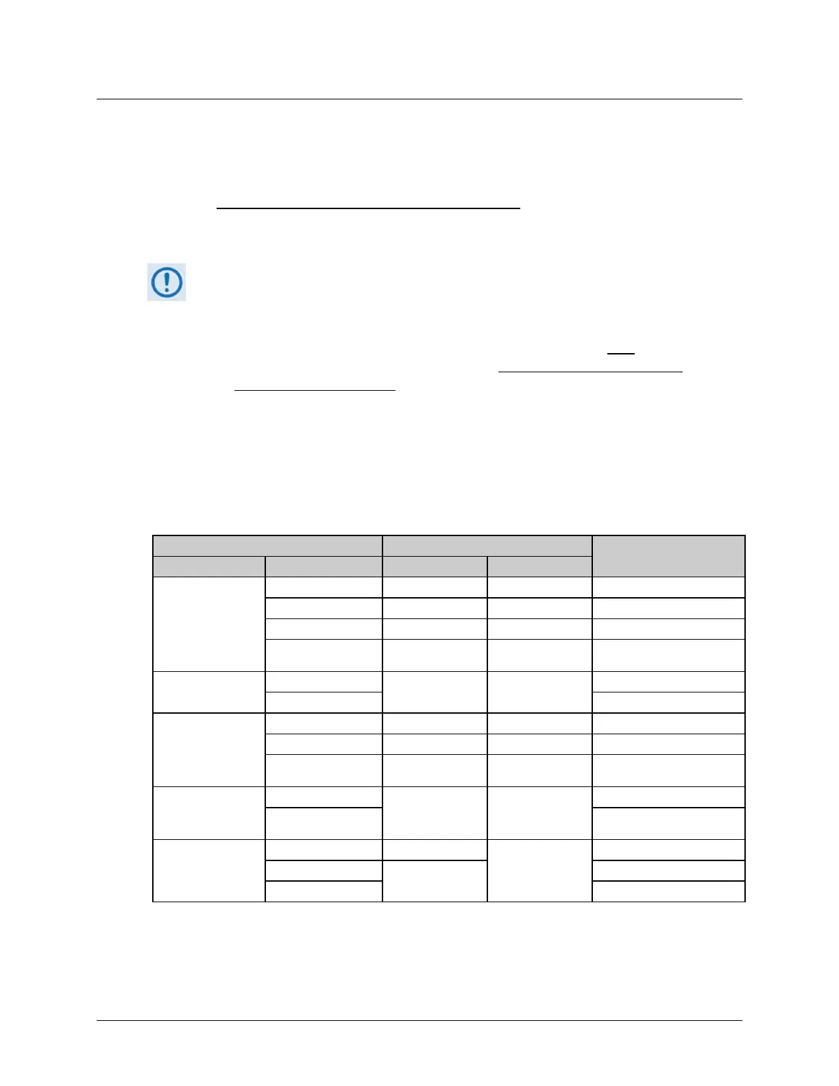
4.10.2 Interface Combinations
The two plug-in interface module slots available in the CDM-700 allow for many possible
ijnterface card combinations. The Switch can cover many, but not all, of these combinations.
Table 4-4 details the CDM-700 interface card combinations that are compatible with the Switch.
Table 4-4. CDM-700 Interface Card Combinations
CDM-700 Modem Configuration 1:N CRS-300 Configuration
Comments
Interface Slot 1 Interface Slot 2 TMI Card RMI Card
G.703 (CDI-10)
None CRS-345 CRS-306 ---
G.703 (CDI-10) CRS-345 CRS-306 ---
HSSI (CDI-60) Not Supported Not Supported Exceeds backplane capability
GbE (CDI-70) CRS-345 CRS-306
Use wired-around GigE
OC3 Copper (CDI-50)
None
CRS-325 CRS-306
---
GbE (CDI-70) Valid for Redundant modem
HSSI (CDI-60)
None CRS-336 CRS-306 ---
HSSI (CDI-60) None None Exceeds backplane capability
GbE (CDI-70) CRS-336 CRS-306
Use wired-around GigE
GbE (CDI-70)
None
CRS-336 CRS-306
---
GbE (CDI-70)
Use wired-around GigE
(see APPENDIX A)
None
G.703 (CDI-10) CRS-345
CRS-306
---
HSSI (CDI-60)
CRS-336
---
GbE (CDI-70) ---