CRS-300 1:10 Redundancy Switch MN/CRS300.IOM
Modem, RMI/TMI, and Switch Configuration Revision 19
5–2
5.2 Configure Your Modems
5.2.1 Connect Your Modem Power
Connect the power cords of each modem to a power supply and turn all modems ON.
5.2.2 Modem Firmware and Hardware Requirements
All Traffic Modems and the Redundant Modem must be of the same model in order for the
CRS-300 1:10 Redundancy Switch to operate correctly. You must also configure the Redundant
Modem with the same firmware version and installed options as the Traffic Modems, so that it
can properly mimic all installed Traffic Modems in the event of switchover.
Permitted modem models and firmware versions are:
CDM-700
1.2.1, 1.2.4 or later
(Note: When using GigE, F/W Ver. 1.2.3 is not compatible with the Switch)
1.1.9
SLM5650/5650A Firmware and Hardware Requirements: In order to support the desired
redundancy, you must load the appropriate firmware into the SLM-5650/5650A base modem,
Network Processor (if applicable), and Switch. Higher versions of the firmware continue support
for the given interface (i.e. the highest version supports all interfaces).
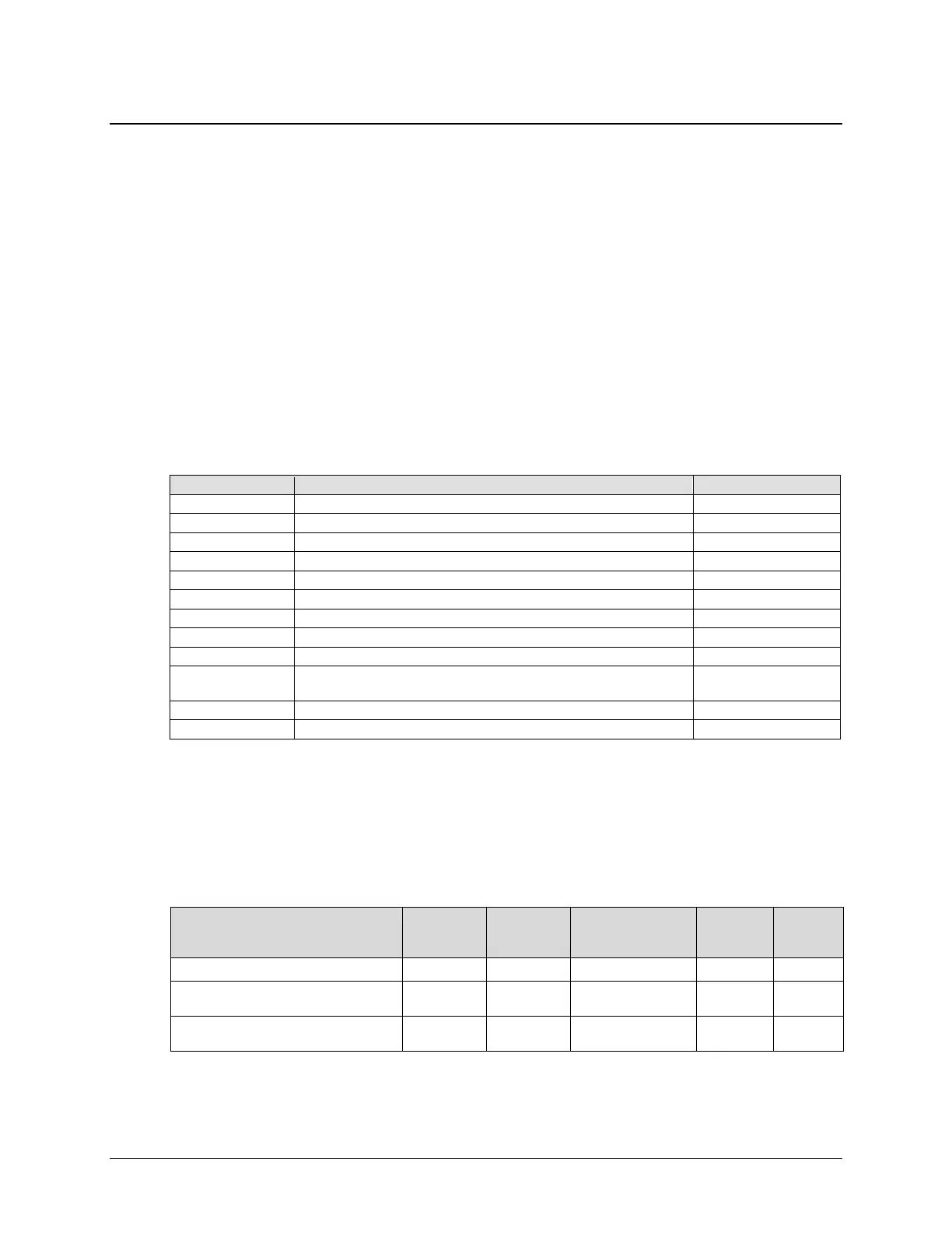
The lowest firmware versions that you require to support a given interface type are:
Interface Type
SLM-5650
Base Modem
SLM-5650A
Base Modem
10/100/1000 Base-T
(GbE) Interface card
Processor
CRS-300
Serial (EIA-232/HSSI) 1.2.4 1.1.1 N/A N/A 2.1.7
Ethernet (Single-port Ethernet Bridge
Mode using 10/100/1000 Base-T card)
1.2.4 1.1.3 1.1.2 N/A 2.1.7
Ethernet (Single-port Ethernet Bridge
Mode using Port 1 of 4-port NP Module)
1.5.1 1.1.8 N/A 1.5.1 2.1.7