CRS-300 1:10 Redundancy Switch MN/CRS300.IOM
Switch Connectors and Pinouts Revision 19
3–8
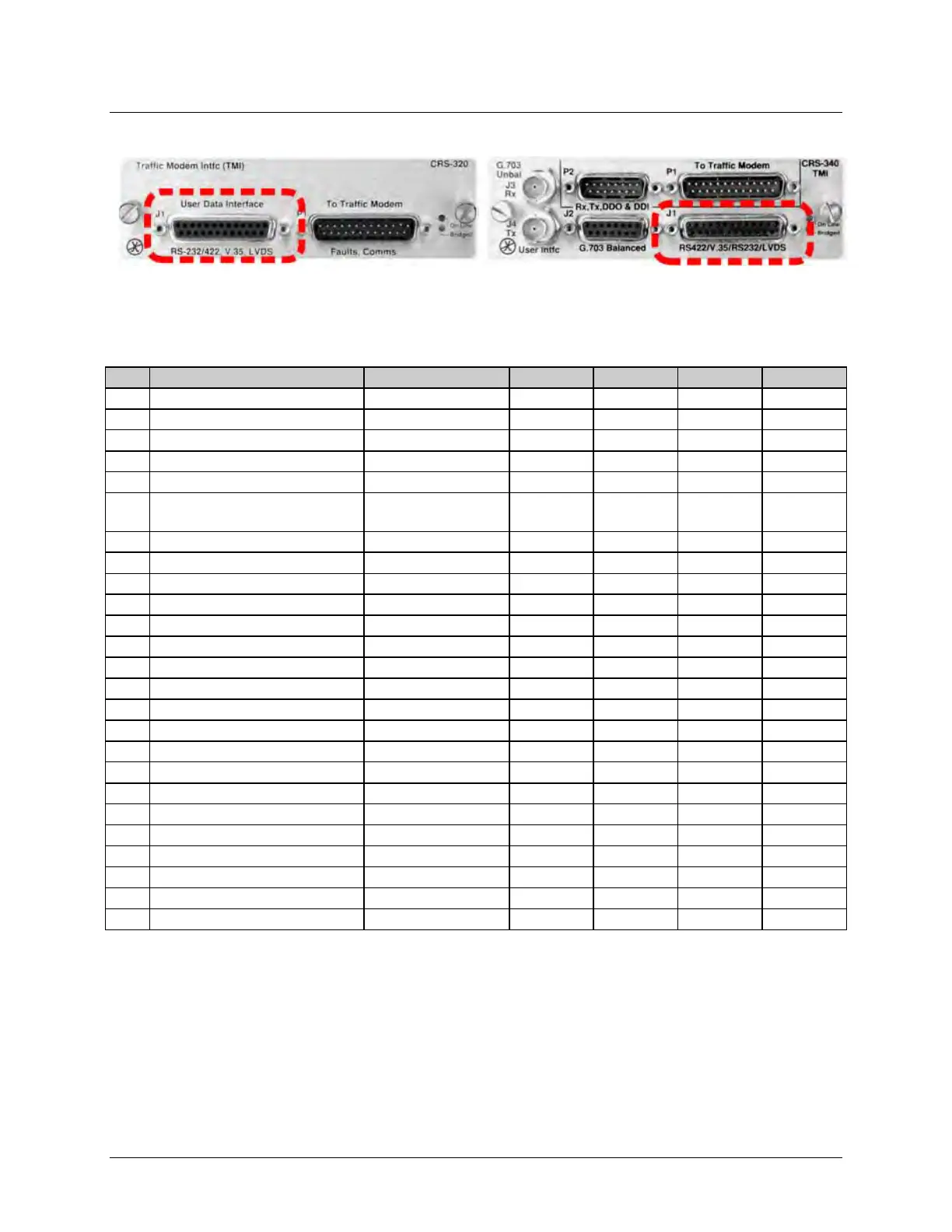
3.2.2.2 EIA-232/422/V.35/LVDS Connector, DB-25F (CRS-320/340)
Table 3-5 indicates the pinout for the DB-25F EIA-232/422/V.35/LVDS User Data Interface
connector – “J1” on the CRS-320 TMI (obsolete), and “J2” on the CRS-340 TMI.
Table 3-5. EIA-232/422/V.35/LVDS Connector
Internal Transmit Clock ‘B’
23
External Carrier Off
(EIA-232 ‘1' or TTL ‘low’)
DTE to Modem --- --- --- ---
Internal Transmit Clock ‘A’
14 Transmit Data ‘B’ DTE to Modem 103 --- SD B SD B
1) “Receiver Ready” is an EIA-232-level control signal on a V.35 interface.
2) Do NOT connect signals to these pins – they are reserved for use by the redundancy system.
3) 'B' signal lines are not used for EIA-232 applications.
4) For X.21 operation, use the EIA-422 pins, but ignore Receive Clock if the modem is DTE, and ignore Transmit clocks if the modem is DCE.