CRS-300 1:10 Redundancy Switch MN/CRS300.IOM
Switch Connectors and Pinouts Revision 19
3–4
3.2 CRS-300 User Data Connectors
Sect. 1.4.3 Plug-in Module (Card) Assemblies
This section illustrates cabling connectors on the basis of available data or traffic interface type.
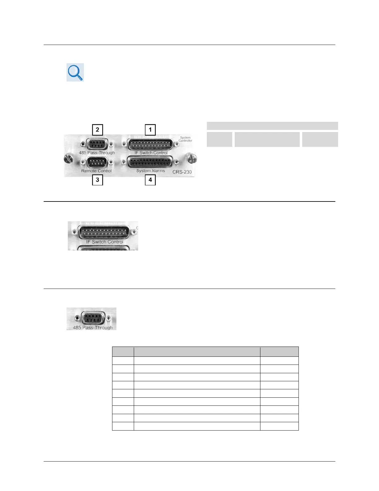
3.2.1 CRS-230 Controller Connectors
CRS-230 System Controller
Feature Connector Description
3.2.1.1 IF Switch Control Connector, DB-25M
Use the DB-25M IF Switch Control connector on the CRS-23 0 for
direct connection to the corresponding cabling connector on the
CRS-280 or CRS-350 switches, when used. This connector supplies
power to these switches, provides the logic interface to drive the
active modem, and decides whether the system is in bridged or backup mode. The CRS-280/350
performs the same bridging and backing up functions of the Tx and Rx IF signals identically to how
the CRS-300 processes the terrestrial data signals.
3.2.1.2 485 Pass-Through Connector, DB-9F
Use the DB-9F 485 Pass-Through connector on the CRS-230 only with
CDM-Qx/QxL modems. It is provided for 2-Wire EIA-485 serial remote
monitor and control of the modems.
Table 3-1. 485 Pass-Through User Data Connector
Pin Signal Function Direction
Reserved - do not connect to this pin
8 EIA-485 Transmit Data B Out
EIA-485 Receive Data A (see note)
EIA-485 Receive Data B (see note)
1 Ground ---