CRS-300 1:10 Redundancy Switch MN/CRS300.IOM
Introduction Revision 19
1–7
1.3 Description of CRS-300 Features
1.3.1 Front Panel
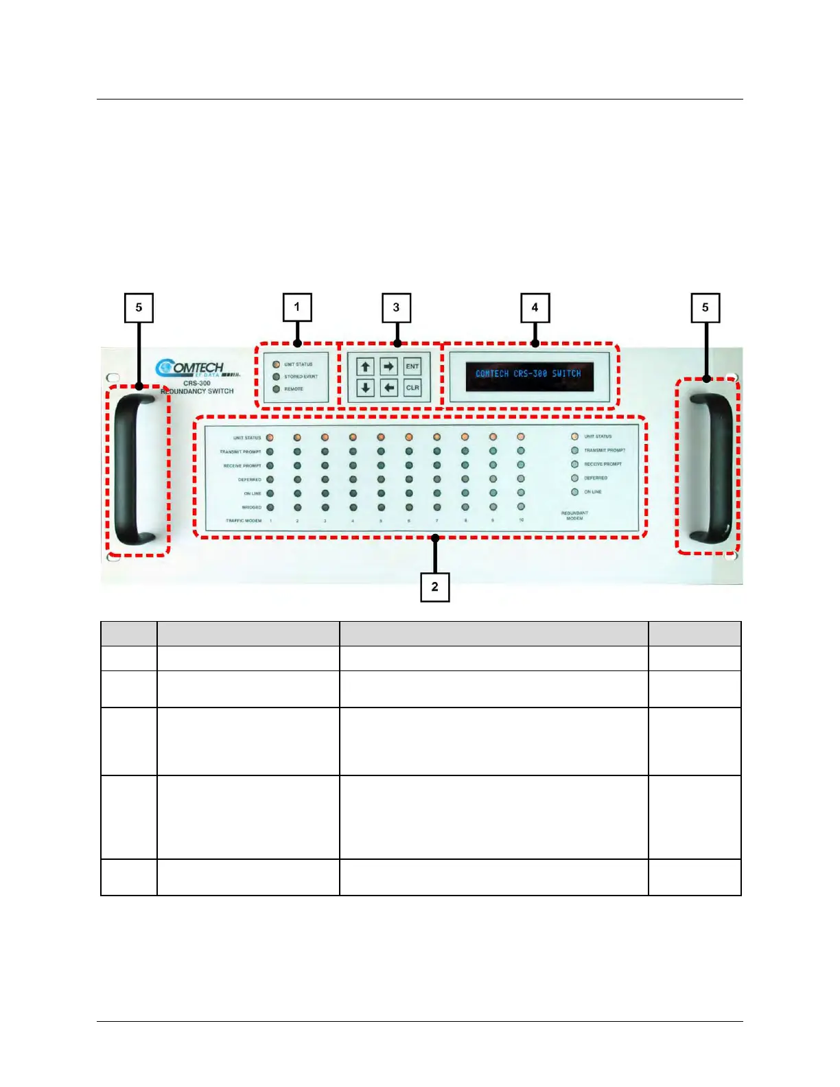
Figure 1-3 shows the CRS-300 Front Panel features, and the manual chapter sections where you
may reference additional information about that feature.
The CRS-300 is constructed as a 4RU-high, rack-mounting chassis that can be freestanding, if
desired.
Feature Description Function Chapter Sect.
1 Unit States LED Indicators These LEDs show a summary status of the Switch. 6.1.2.1
2 Modem Status LED Indicators
These LEDs show a summary status of the Traffic and
Redundant modems.
6.1.2.2
3 Keypad
Use the keypad to enter data. The keypad has six
individual key switches mounted behind a sealed
membrane overlay. The keys have a positive ‘click’ action
that gives tactile feedback.
6.1.1
4
Vacuum Fluorescent Display
(VFD)
The VFD shows data, menus, prompts and messages.
The VFD is an active display with adjustable brightness. It
shows two lines of 24 characters each. Nested menus
show all available options and prompts that guide you in
carrying out required actions.
6.1.3
5 Rack Handles
In a rack enclosure, these handles help you install and
remove the unit.
2.2
Figure 1-3. CRS-300 Front Panel Features