CRS-300 1:10 Redundancy Switch MN/CRS300.IOM
Switch Connectors and Pinouts Revision 19
3–18
3.3.2.1.1 AC Operation – Power Application
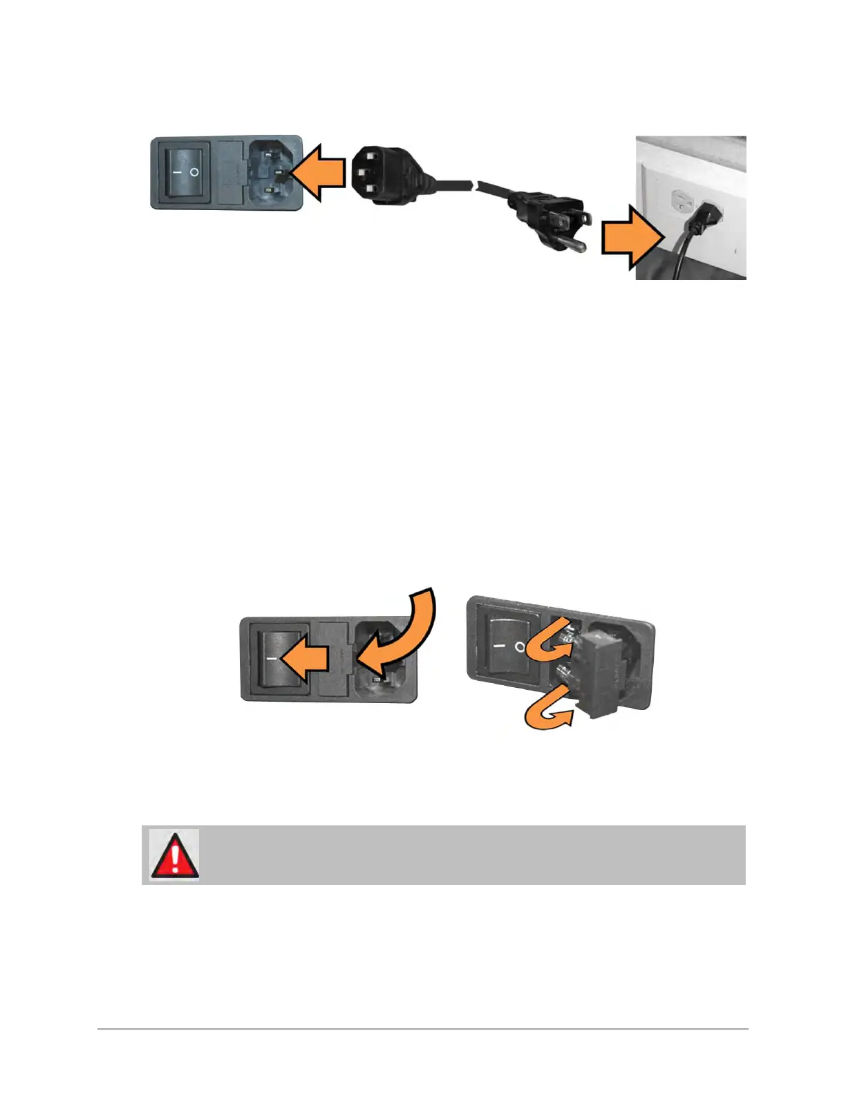
Figure 3-6. Apply AC Power
Apply AC power to the CRS-300 (Figure 3-6, typical for each module). Do these steps:
• First, plug the provided AC power cord female end into the unit.
• Then, plug the AC power cord male end into the user-supplied power source.
• Finally, switch the module ON.
3.3.2.1.2 AC Operation – Fuse Replacement
For AC operation, the Switch uses two common 5mm x 20mm Slow-blow fuses – one each for
line and neutral connections. The fuses are contained within a fuse holder that is press-fit into
the body of the IEC power module (Figure 3-7).
Figure 3-7. Replace the AC Fuses
Do these steps to replace the module fuse(s) (Figure 3-7, typical for each module):
WARNING! DISCONNECT THE POWER SUPPLY BEFORE PROCEEDING!
• First, unseat the fuse holder from the IEC power module:
o Use the slot to pry the holder outward from the IEC power module.