CRS-300 1:10 Redundancy Switch MN/CRS300.IOM
Modem, RMI/TMI, and Switch Configuration Revision 19
5–13
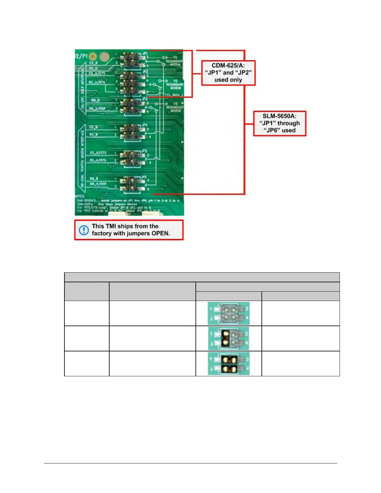
Figure 5-5. CRS-316 “JP1” through “JP6” Jumper Detail (As Shipped)
Table 5-2. CRS-316 “JP1” Jumper Settings
User Interface Jumper “JP1”
Modem Control Signal Settings
CDM-625/A
CS_B & RS_B Signals
Not Connected
N/A
(Note: TMI as shipped)
CDM-625/A
Loop Connected
at User DB-25 Connector
‘1’ to ‘3’
SLM-5650A
CS_B & RS_B
Routed to online modem
‘1’ to ‘2’
‘3’ to ‘4’