CRS-300 1:10 Redundancy Switch MN/CRS300.IOM
Introduction Revision 19
1–8
1.3.2 Rear Panel
• Chapter 3. SWITCH CONNECTORS AND PINOUTS
• Chapter 5. MODEM, RMI/TMI,
AND SWITCH CONFIGURATION
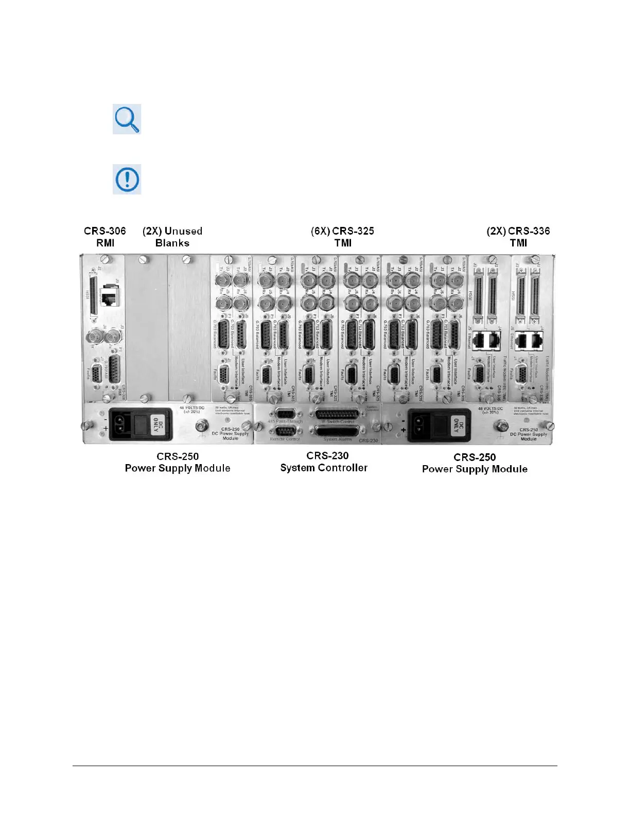
Figure 1-4 shows the back panel of the CRS-300 with an example array of installedTMI cards.
Because the RMI can have the capability for several TMIs, depending on user
requirements the CRS-300 may be able to use several different TMI cards
simultaneously.
Figure 1-4. CRS-300 Rear Panel – Configuration Example