CRS-300 1:10 Redundancy Switch MN/CRS300.IOM
Modem, RMI/TMI, and Switch Configuration Revision 19
5–11
5.3 RMI Card Configuration Reference
Comtech EF Data provides this RMI Card Configuration Reference for RMI
identification purposes only. Comtech EF Data ships all RMI cards pre-configured –
they require no user adjustments.
Comtech EF Data ships the CRS-305, CRS-306, and CRS-307 RMI cards pre-set for proper
operation. Each card shares a common printed circuit board (CEFD P/N PC/11494x); what
distinguishes the cards from one another is the configuration of front panel connectors, and
configuration of the Jumper “JMP1” setting on the PCB.
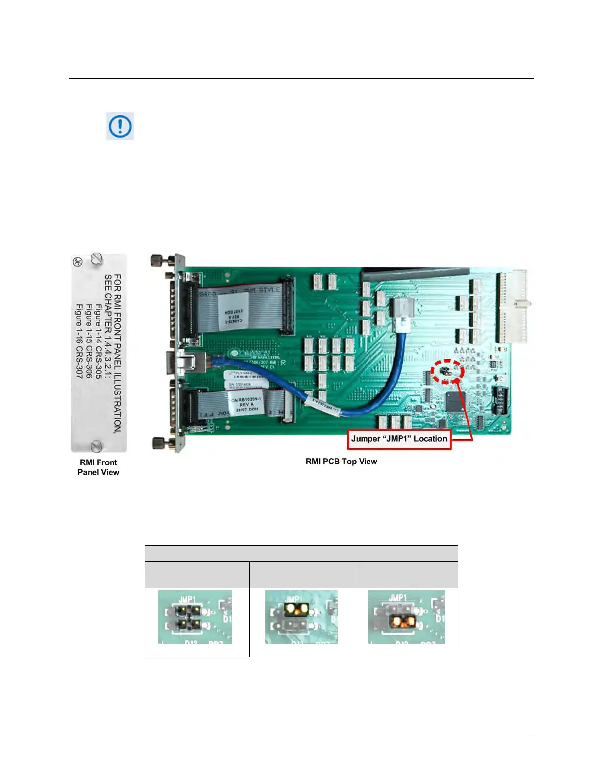
Figure 5-3 identifies the “JMP1” jumper location that typical for all RMI PCBs.
Figure 5-3. CEFD P/N PC/11494x RMI PCB (CRS-307 shown)
Table 5-1 defines the Jumper “JMP1” settings, as shipped from the factory, for each RMI card.
Table 5-1. RMI “JMP1” Jumper Settings (As Shipped)
“JMP1” Jumper Setting – AS SHIPPED
CRS-306
Pins ‘1’ to ‘2’ Jumped
CRS-307
Pins ‘3’ to ‘4’ Jumped