CRS-300 1:10 Redundancy Switch MN/CRS300.IOM
Modem, RMI/TMI, and Switch Configuration Revision 19
5–12
5.4 TMI Card Configuration Reference
This subsection shows the modem-specific configuration settings for each TMI card. Comtech EF
Data ships these TMIs with their jumpers pre-set for proper operation.
5.4.1 EIA-530 Interfaces via the CRS-316 TMI
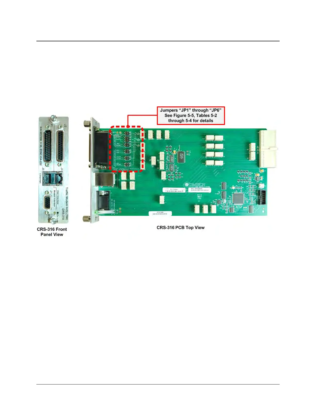
Figure 5-4 shows the CRS-316 TMI (CEFD P/N PL/12498, Rev ‘A’ or later).
Figure 5-4. CRS-316 EIA-530 TMI Card (Jumpers Shown Open)
Figure 5-5 shows the jumper section of the CRS-316 TMI PCB. Comtech EF Data ships these TMIs
pre-set with jumpers “JP1” through “JP6” open.
Table 5-2, Table 5-3, and Table 5-4 define the jumper settings for the modem-specific control
signal configurations:
• For CDM-625/A modems – the permitted settings for jumpers “JP1” and “JP2” only are:
o For ‘RTS to CTS’ Loop – Pin ‘1’ to Pin ‘3’ (“JP1” to “JP2”) jumped
o For ‘RTS to Control TX IF Mute’ operation for online modem – Pin ‘3’ to Pin ‘5’ (“JP2”)
jumped
• For SLM-5650A modems – the settings for jumpers “JP1” thru “JP6” are:
o Pin ‘1’ to Pin ‘2’ jumped
o Pin ‘3’ to Pin ‘4’ jumped