EasyManua.ls Logo

Comtech EF Data CRS-300 - Balanced G.703 Connector, DB-15 F (CRS-325;330;340); Table 3-8. Balanced G.703 Connector

Comtech EF Data CRS-300
298 pages
Print Icon
To Next Page IconTo Next Page
To Previous Page IconTo Previous Page
Loading...
CRS-300 1:10 Redundancy Switch MN/CRS300.IOM
Switch Connectors and Pinouts Revision 19
3–10
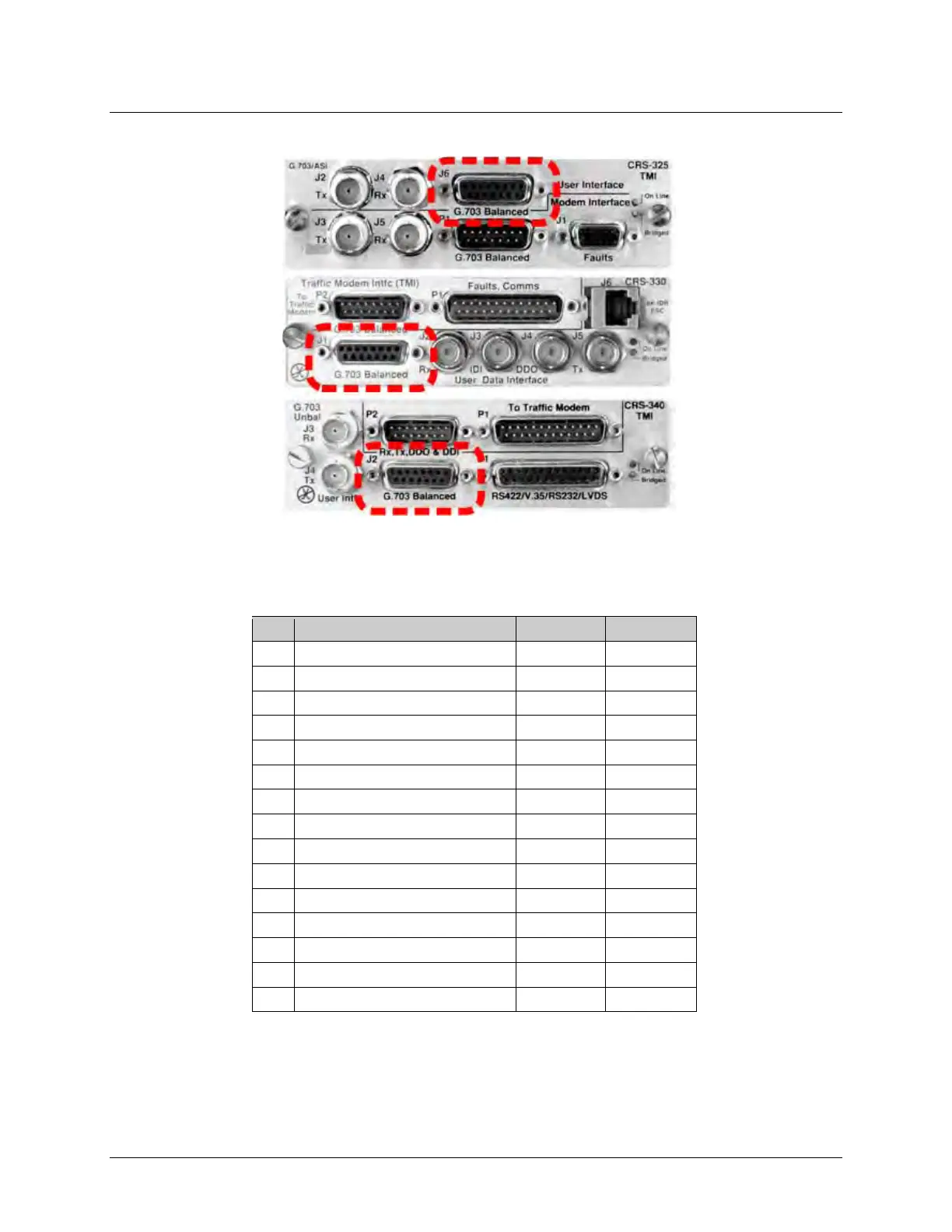
3.2.2.5 Balanced G.703 Connector, DB-15F (CRS-325/330/340)
See Table 3-8 for the pinout for the DB-15F Balanced G.703 User Data Interface connectors – “J6
on the CRS-325 TMI; J1on the CRS-330 TMI; and J2on the CRS-340 TMI.
Table 3-8. Balanced G.703 Connector
Pin
Signal Function
Name
Direction
8
Not Used
15 Not Used
7 Not Used
14
Not Used
6
Insert Data Input (+)
IDI+
In
13
Insert Data Input (-)
IDI
In
5
Drop Data Output (+)
DDO+
Out
12
Drop Data Output (-)
DDO
Out
4
Ground
GND
11*
Rx, Insert Data Output (+)
IDO+
Out
3* Rx, Insert Data Output (-) IDO Out
10
Not Used
2
Ground
GND
9*
Tx, Drop Data Input (+)
DDI+
In
1*
Tx, Drop Data Input (-)
DDI
In
* Use for all non-Drop and Insert and T2/E2 balanced applications.

Table of Contents