CRS-300 1:10 Redundancy Switch MN/CRS300.IOM
Modem, RMI/TMI, and Switch Configuration Revision 19
5–7
See Chapter 5. FRONT PANEL OPERATION in the SLM-5650 or SLM-5650A Installation
and Operation Manual for detailed information about using the modem front panel
menus.
5.2.4.4 Configure Switch-to-CDM-Qx/QxL 1:N Redundancy
The Switch-to-CDM-Qx/QxL redundancy configuration uses an external EIA-485 multi-drop
communication cable.
You can configure the CDM-Qx/QxL in many different ways – i.e., one-to-four modulators, one-
to-four demodulators, a mix of one or more modems, etc. For a Switch application, you should
configure the CDM-Qx/QxL only as one modem consisting of one modulator card and one
demodulator card; the pair must be grouped to act as a single modem.
See the CDM-Qx/QxL Installation and Operation Manual for detailed configuration
information.
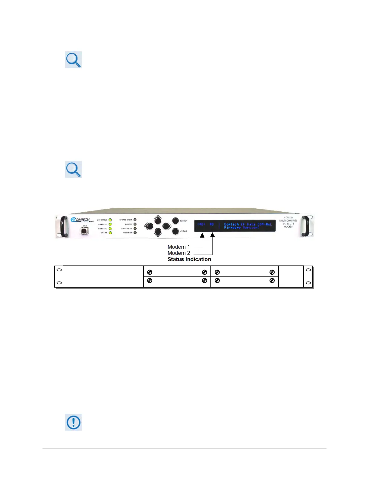
As shown in Figure 5-1, Modem 1 resides in Slots 1 and 2. Slots 3 and 4 comprise Modem 2. The
Switch can use either modem.
(TOP) Front Panel
(BOTTOM) Rear Panel Schematic
Figure 5-1. CDM-Qx/QxL Serial Communication Configuration Example
The CDM-Qx/QxL chassis has a configurable EIA-485 base address, applicable to Modem 1, and
an offset that is added to the base-address when addressing Modem 2 or greater. You must use
the CDM-Qx/QxL Front Panel menu to select the EIA-485 addresses (identified on the menus as
RS-485). Use the ◄ ► arrow keys to select CONFIG
REMOTE. Make sure to press ENTER to
save your changes.
The Switch address for each CDM-Qx/QxL Traffic Modem is based on which TMI it is attached to,
with addresses specified in increments of 100.
For example – for a Switch with address 0, the CDM-Qx/L on TMI 1 is assigned address 0100; the
TMI 2 address is 0200, and so forth, up to address 1000 for TMI 10.
It is important that you understand the addressing scheme before proceeding. The
RMI uses address 1100.