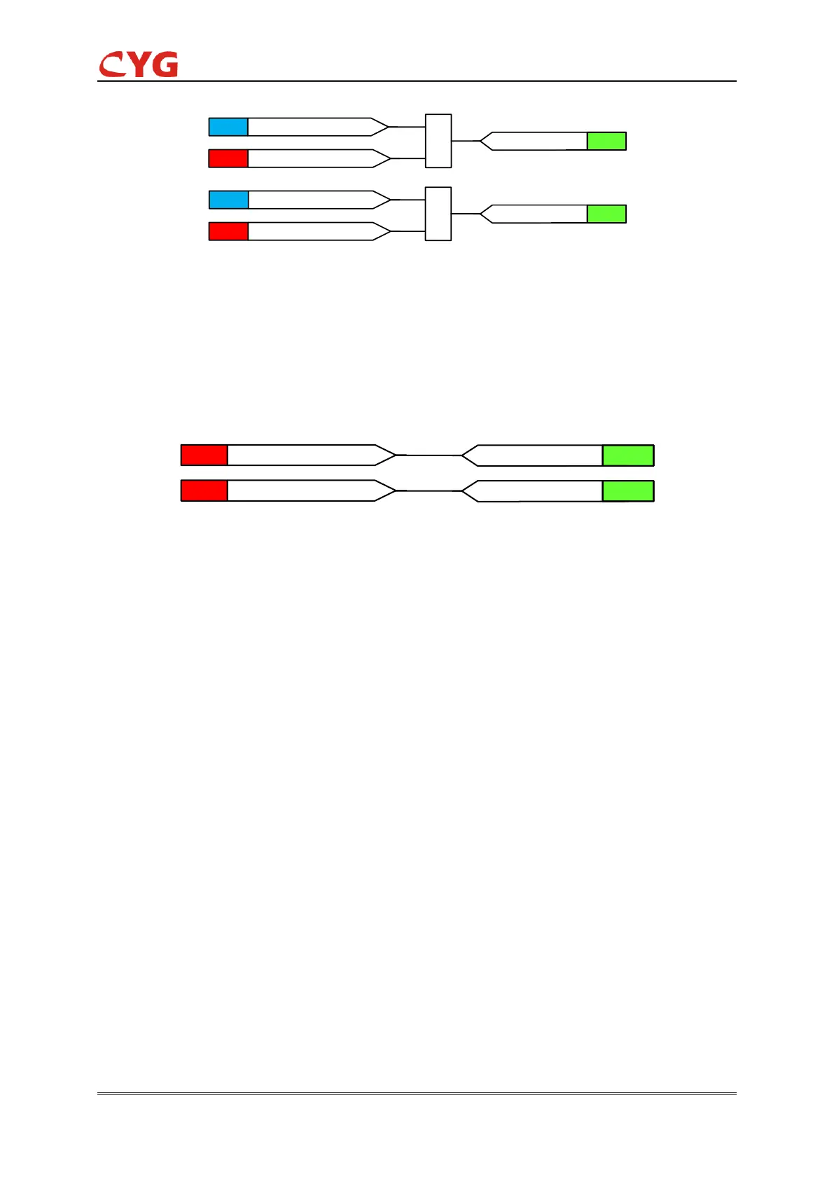
Figure 3.34-4 Diagram of incoming line live voltage logic
4) "Incoming line live current” means the current at one phase of incoming line of operational
power supply is more than incoming line live current setting value. This setting value
should be less than minimum load current, or backup power automatic switching may
malfunction in case of CT three-phase line-break of operational power supply.
Figure 3.34-5 Diagram of incoming line dead current logic
3.34.2.2 Backup power automatic switching of incoming line 1 (BPAS1)
Discharge Conditions
The logic diagram of the discharge condition of BPAS1 is shown in Figure 3.34-6.