Installation
338 PRS-7367
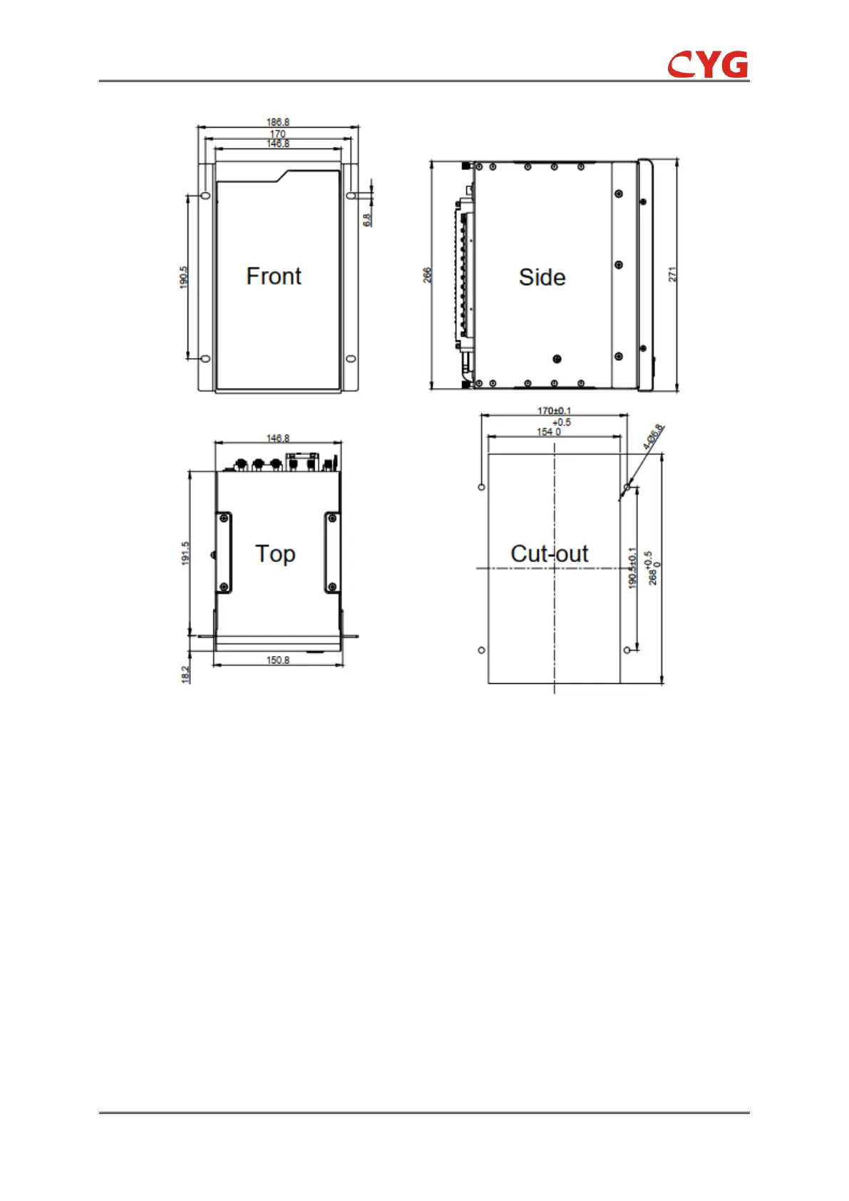
Figure 11.6-1 Dimensions of this relay and the cut-out in the cubicle (unit: mm)
11.7 Electrical Installation and Wiring
11.7.1 TA Circuit Connection
According to the wiring diagram of the device, connect the terminal block of rear AC module with
the CT loop using multiple wires, of which the cross-sectional area should be 2.5 ~ 4.0mm
2
.
11.7.2 Power Supply, TV, BI and BO, Signal Wiring
According to the wiring diagram of the device, connect the AC, Phoenix terminal of module and the
terminal block in the cubicle side with multiple wires.
DC voltage power supply wiring power +, power - should be distinguish in different colors, for
example power + (brown), power - (blue).
Power supply, binary inputs & outputs: stranded conductor, 1.0mm
2
~ 2.5mm
2
.
AC voltage inputs: stranded conductor, 1.5mm
2
.