Protection Functions
62 PRS-7367
Table 3.6-3 Options for dead-line detection
The dead-line detection function is disabled. This operation mode must be
applied when voltage transformers are located on the bus side of the circuit
breaker.
The dead-line detection function is enabled and based solely on the under
voltage condition. A dead-line condition is declared, if all the phase voltages are
below the SOTF_Vol_Dead_Line setting. The dead line is detected if the
dead-line condition is declared and simultaneously no fault is detected by the
SOTF_Str and SOTF_Str_Dly inputs. The dead-line condition is signaled to the
SOTF control after the delay defined with the SOTF_Dead_Line_T setting.
The dead-line detection function is enabled and based solely on the undercurrent
condition. A dead-line condition is declared, if all the phase currents are below the
SOTF_Cur_Dead_Line setting. The dead line is detected if the dead-line
condition is declared and simultaneously no fault is detected by the SOTF_Str
and SOTF_Str_Dly inputs. The dead-line condition is signaled to the SOTF
control after delay defined with the SOTF_Dead_Line_T setting.
The dead-line detection function is enabled and based on undercurrent and
under voltage condition. A dead line condition is declared, if all the phase currents
are below the Current dead Lin Val setting and simultaneously all phase voltages
are below the Voltage dead Lin Val setting. The dead line is detected if the
dead-line condition is declared and simultaneously no fault is detected by the
SOTF_Str and SOTF_Str_Dly inputs. The dead-line condition is signaled to the
SOTF control after delay defined with the SOTF_Dead_Line_T setting.
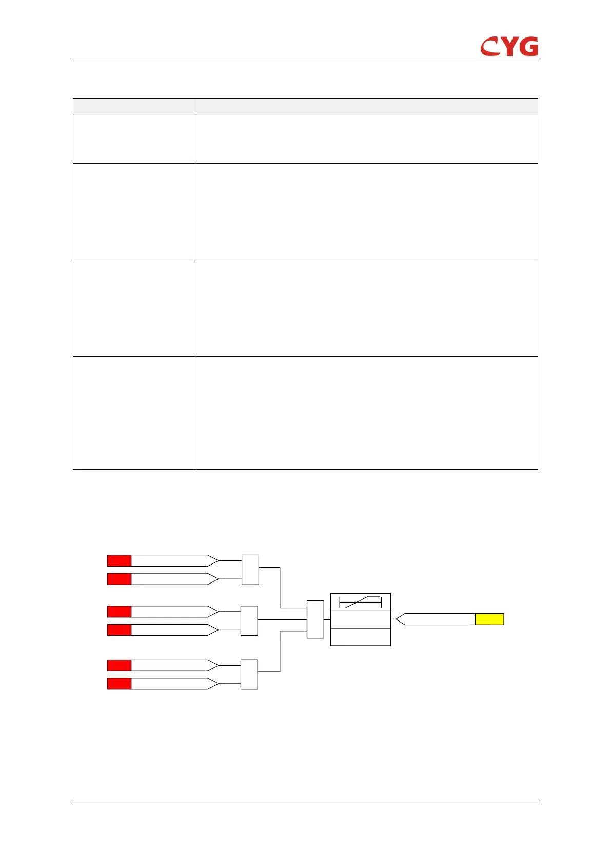
SOTF detection
The SOTF detection logic diagram is shown as below:
&
1
Ua <SOTF_Vol_Dead_Line
ANA
Ia >SOTF_Cur_ Dead_LineANA
&
Ub < SOTF_Vol_Dead_Line]
ANA
Ib >SOTF_Cur_ Dead_ Line
ANA
&
Uc <SOTF_Vol_ Dead_ Line]
ANA
Ic >SOTF_Cur_ Dead_ Line]
ANA
0
SOTF_Situation
FLG
SOTF_CurVol_Det_T
Figure 3.6-4 SOTF detection logic diagram
The purpose of this module is to detect the switch onto fault situation based on the current and
voltage measurements. If the voltage, in any of the phases, is below the SOTF_Vol_Dead_Line