Protection Functions
PRS-7367 63
setting and simultaneously the current in the same phase exceeds the SOTF_Cur_Dead_Line
setting, the SOTF situation is signaled to SOTF control module after the set SOTF_CurVol_Det_T.
SOTF control
The SOTF control activated and reset diagram is shown below:
Figure 3.6-5 SOTF control activated and reset
The SOTF control module needs to be activated before the operation is possible in the
switch-onto-fault situation. There are two ways to activate the SOTF control module.
• By CB position (circuit breaker is open position, CB_CLOSE=0)
• By the dead-line condition received from the dead-line detection
The dead-line detection should be used only when the voltage transformers are located on the line
side of the circuit breaker.
When the CB position is open or the dead-line condition is detected, the SOTF control module
becomes active. The reset timer is started when CB position is closed or the dead-line condition
disappears. Thus the module becomes inactive after the set SOTF_Reset_T is exceeded.
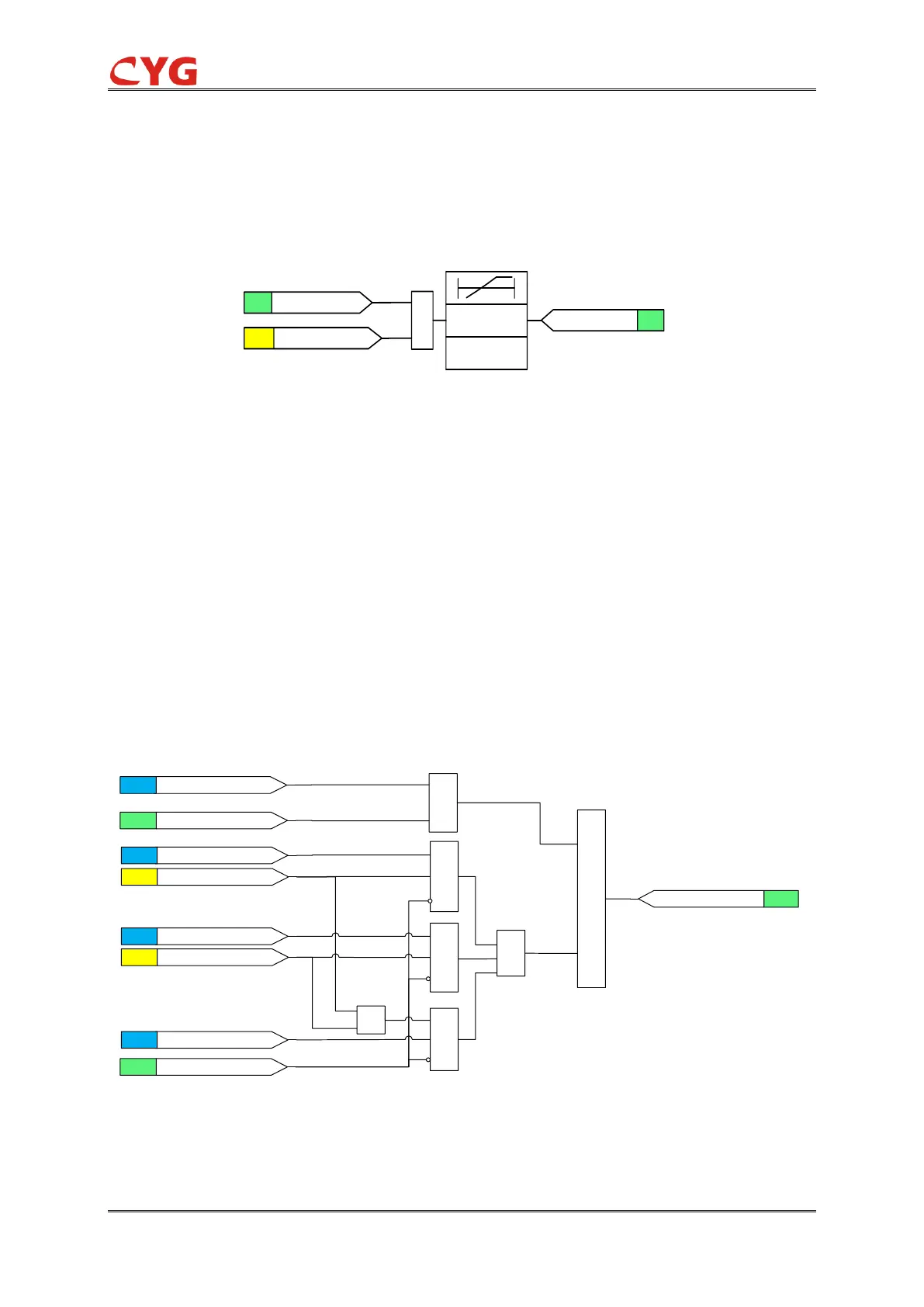
The functional module diagram is shown as below:
Figure 3.6-6 Functional module diagram
When the SOTF control module is active, the SOTF_Op_Mod setting defines the operation criteria
for the detection of a switch-onto-fault condition. The detection can be based on the external start