GB
© Danfoss | FHEC | 2018.06 | 13
VIMCG30F / 088N3678
Installation Guide Danfoss Icon™ Master Controller 24 V
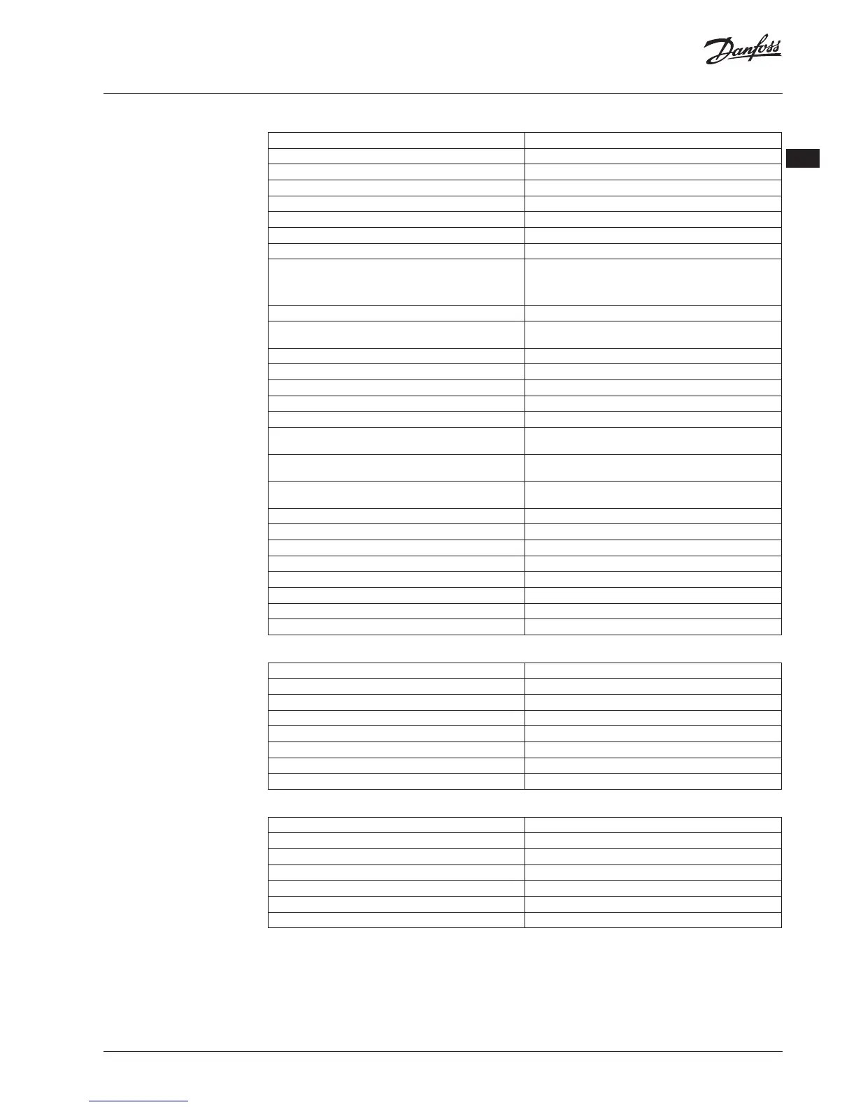
Master Controller 24V and Expansion Module (optional)
Supply voltage 220-240 VAC
Supply frequency 50/60 Hz
Output voltage, actuators 24 VDC
Max. power consumption per actuator output 2 W
Number of actuator outputs (1 actuator per output terminal) 10 or 15 depending on type
Output voltage, thermostats 24 VDC
Stand-by consumption per thermostat 0.2 W
Max. number of thermostats 10 or 15 depending on type
Max. length of wire from master controller to a 24 V thermostat
(depends on cable type used)
If 2x2x0.6mm
2
STP/UTP: 100 m
If 2x0.5mm
2
: 150 m
If > 2x0.75mm
2
: 200 m
Stand-by consumption, Master Controller < 2 W
Max. power consumption, excluding use of PWR 1 and PWR 2
outputs
< 50 W
Internal protection (fuse, non-replacable) 2.5 A
Output “Relay” Micro-disconnection (Type 1.B action), Max. 2 A load
Actuator outputs, type Electronic disconnection (Type 1.Y action)
Output “PWR 1”, type and rated max. output Micro-interruption (Type 1.C action)
Output “PWR 2”, type and rated max. output Type: Permanent output, Always live 230 V, Max. 50W
Output “PWR 3” (optional, on Expansion module — used for dew
point sensor)
24 VDC, max. 1 W
Input “1” (optional, on Expansion module — use varies acc. to
application chosen)
Ext. switch input (internal 24V pull-up)
Input “2” (optional, on Expansion module — use varies acc. to
application chosen)
Ext. switch input (internal 24V pull-up)
Input “3”, sensor input (optional, on Expansion module) External sensor, PT 1000 (Danfoss ESM 11)
Dimensions & weight W:370mm H:100mm D:53mm
Conformity declared acc. to following directives LVD, EMC, RoHS and WEEE
Purpose of control Individual electronic room temperature control
Method of providing earthing Factory tted power cord, incl. PE-conductor
Encapsulation (IP Class) IP 20
Protection class Class I
Ambient temperature range, continious use 0 to + 50 °C
Wireless Thermostat
Purpose of control Room thermostat for room temperature control
Ambient temperature range, continious use 0 to + 40 °C
Frequency 869 MHz
Transmission power <2.5 mW
Encapsulation (IP Class) IP 21
Supply voltage 2 x 1.5 V AA-Alkaline batteries
Conformity declared acc. to following directives RED, RoHS, WEEE
Protection class Class III
24V Wired Thermostat
Purpose of control Room thermostat for room temperature control
Ambient temperature range, continious use 0 to + 40 °C
Encapsulation (IP Class) IP 21
Supply voltage 24 VDC
Conformity declared acc. to following directives EMC, RoHS, WEEE
Protection class Class III
External sensor NTC type, 47 k @ 25°C (Optional, 088U1110)
 Loading...