No Flow Detection:
This function is used for detecting a no flow situation in pump systems where all valves can be closed. Can be used both when controlled by the integrated
PI controller in the frequency converter or an external PI controller. Actual configuration must be programmed in par. 1-00
Configuration Mode
.
Configuration mode for
- Integrated PI Controller: Closed Loop
- External PI Controller: Open Loop
NB!
Carry out No Flow tuning before setting the PI controller parameters!
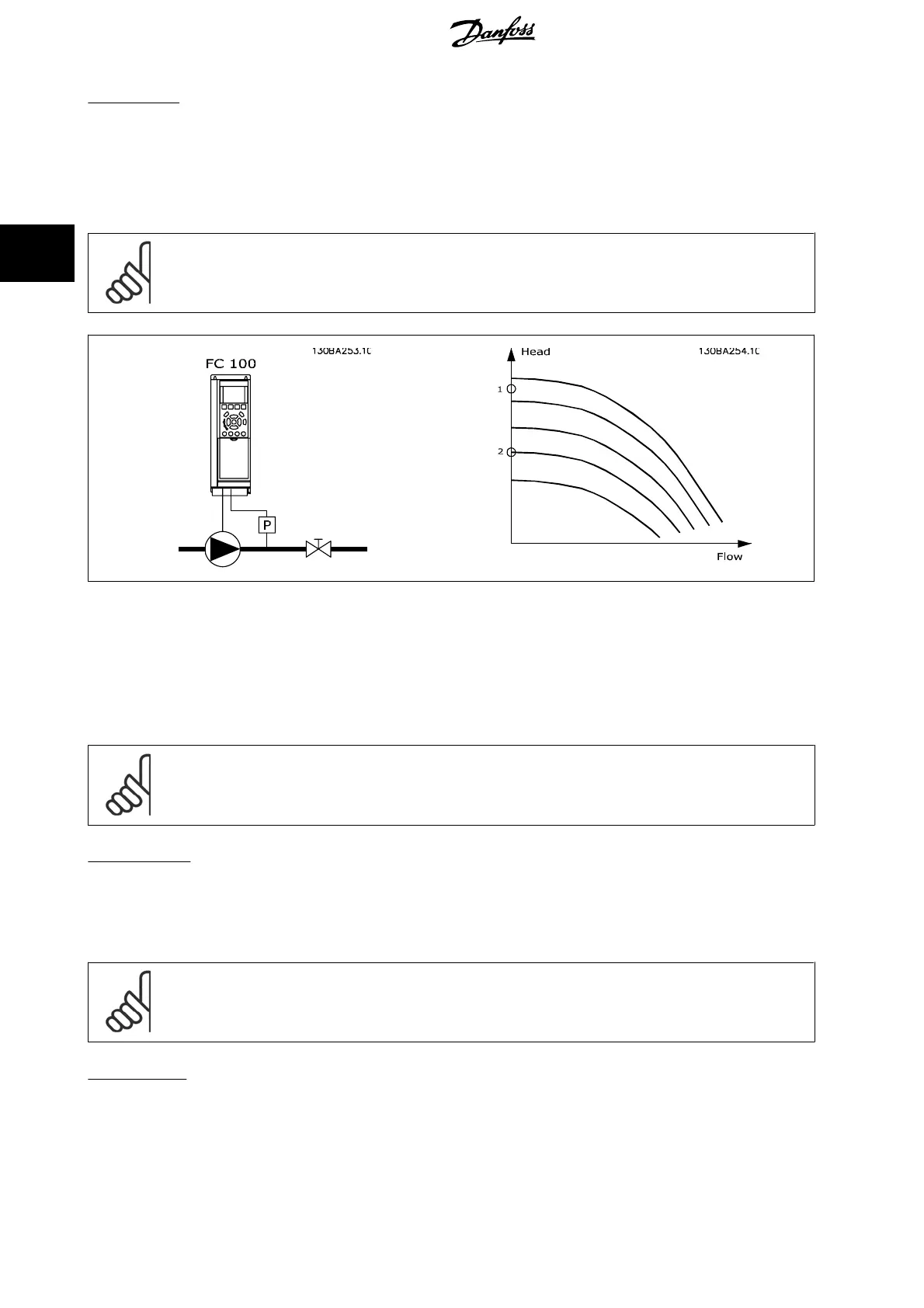
No Flow Detection
is based on the measurement of speed and power. For a certain speed the frequency converter calculates the power at no flow.
This coherence is based on the adjustment of two sets of speed and associated power at no flow. By monitoring the power it is possible to detect no flow
conditions in systems with fluctuating suction pressure or if the pump has a flat characteristic towards low speed.
The two sets of data must be based on measurement of power at approx. 50% and 85% of maximum speed with the valve(s) closed. The data are
programmed in the parameter group 22-3*. It is also possible to run a
Low Power Auto Set Up
(par. 22-20
Low Power Auto Set-up
) automatically stepping
through the commissioning process and also automatically storing the data measured. The frequency converter must be set for Open Loop in
par. 1-00
Configuration Mode
, when carrying out the Auto Set Up (See No Flow Tuning parameter group 22-3*).
NB!
If to use the integrated PI controller, carry out No Flow tuning before setting the PI controller parameters!
Low speed detection:
Low Speed Detection
gives a signal if the motor is operating with minimum speed as set in par. 4-11
Motor Speed Low Limit [RPM]
or par. 4-12
Motor
Speed Low Limit [Hz]
. Actions are common with No Flow Detection (individual selection not possible).
The use of Low Speed Detection is not limited to systems with a no flow situation, but can be used in any system where operation at minimum speed
allows for a stop of the motor until the load calls for a speed higher than minimum speed, e.g. systems with fans and compressors.
NB!
In pump systems ensure that the minimum speed in par. 4-11
Motor Speed Low Limit [RPM]
or par. 4-12
Motor Speed Low Limit
[Hz]
has been set high enough for detection as the pump can run with a rather high speed even with valves closed.
Dry pump detection:
No Flow Detection
can also be used for detecting if the pump has run dry (low power consumption-high speed). Can be used with both the integrated
PI controller and an external PI controller.
The condition for Dry Pump signal:
- Power consumption below no flow level
3 Parameter Description VLT
®
HVAC Drive Programming Guide
202
MG.11.C9.02 - VLT
®
is a registered Danfoss trademark
3