External stop signals activated by means of control signals or a serial bus will override a 'start' command via the LCP.
The following control signals will still be active when [Hand on] is activated:
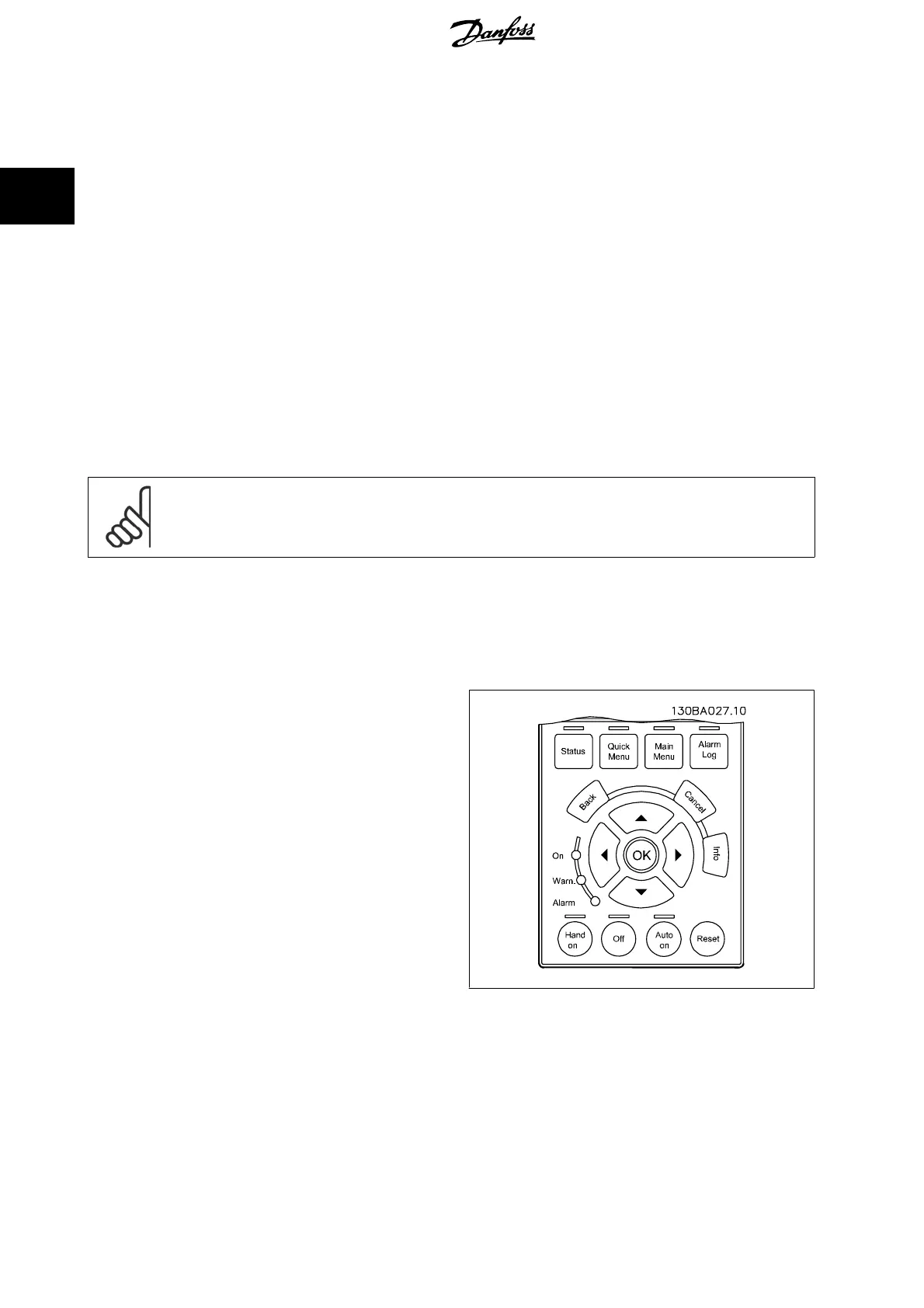
• [Hand on] - [Off] - [Auto on]
• Reset
• Coasting stop inverse
• Reversing
• Set-up select lsb - Set-up select msb
• Stop command from serial communication
•Quick stop
•DC brake
[Off] stops the connected motor. The key can be selected as
Enable
[1] or
Disable
[0] via par. 0-41
[Off] Key on LCP
.
If no external stop function is selected and the [Off] key is inactive the motor can be stopped by disconnecting the mains supply.
[Auto on] enables the frequency converter to be controlled via the control terminals and/or serial communication. When a start signal is applied on the
control terminals and/or the bus, the frequency converter will start. The key can be selected as
Enable
[1] or
Disable
[0] via par. 0-42
[Auto on] Key on
LCP
.
NB!
An active HAND-OFF-AUTO signal via the digital inputs has higher priority than the control keys [Hand on] [Auto on].
[Reset] is used for resetting the frequency converter after an alarm (trip). It can be selected as
Enable
[1] or
Disable
[0] via par. 0-43
[Reset] Key on
LCP
.
2.1.3 Quick Transfer of Parameter Settings between Multiple Frequency Converters
Once the set-up of a frequency converter is complete, we recommend
that you store the data in the LCP or on a PC via MCT 10 Set-up Software
Tool.
Data storage in LCP:
1. Go to par. 0-50
LCP Copy
2. Press the [OK] key
3. Select “All to LCP”
4. Press the [OK] key
All parameter settings are now stored in the LCP indicated by the progress bar. When 100% is reached, press [OK].
2 How to Programme VLT
®
HVAC Drive Programming Guide
20
MG.11.C9.02 - VLT
®
is a registered Danfoss trademark
2