Par
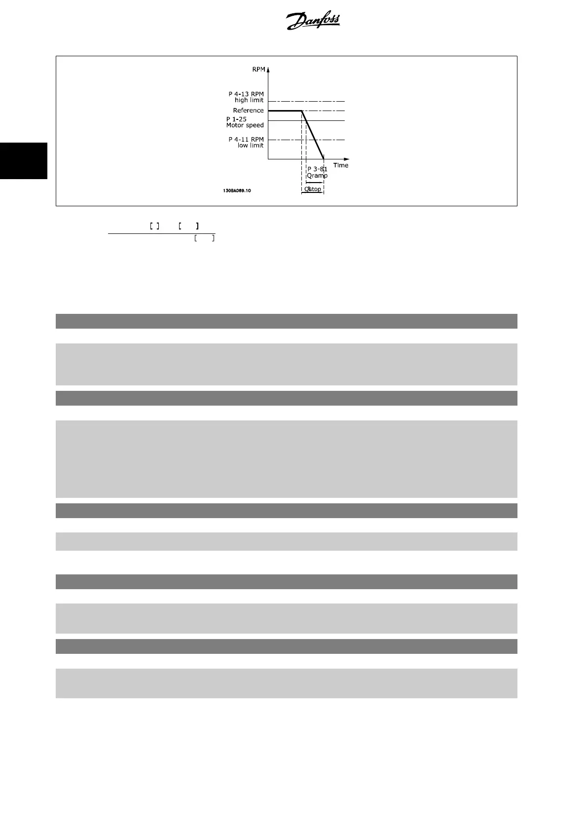
. 3 − 81 =
t
Qstop
s
x
n
s
RPM
Δ
jog
ref
(
par
. 3 − 19
)
RPM
3.5.6 3-9* Digital Pot.Meter
The digital potentiometer function allows the user to increase or decrease the actual reference by adjusting the set-up of the digital inputs using the
functions INCREASE, DECREASE or CLEAR. To activate the function, at least one digital input must be set up to INCREASE or DECREASE.
3-90 Step Size
Range: Function:
0.10 %* [0.01 - 200.00 %] Enter the increment size required for INCREASE/DECREASE, as a percentage of the synchronous
motor speed, n
s
. If INCREASE/ DECREASE is activated the resulting reference will be increased /
decreased by the amount set in this parameter.
3-91 Ramp Time
Range: Function:
1.00 s [0.00 - 3600.00 s] Enter the ramp time, i.e. the time for adjustment of the reference from 0% to 100% of the specified
digital potentiometer function (INCREASE, DECREASE or CLEAR).
If INCREASE / DECREASE is activated for longer than the ramp delay period specified in
par. 3-95
Ramp Delay
the actual reference will be ramped up / down according to this ramp time.
The ramp time is defined as the time used to adjust the reference by the step size specified in
par. 3-90
Step Size
.
3-92 Power Restore
Option: Function:
[0] * Off Resets the Digital Potentiometer reference to 0% after power up.
[1] On Restores the most recent Digital Potentiometer reference at power up.
3-93 Maximum Limit
Range: Function:
100 %* [-200 - 200 %] Set the maximum permissible value for the resultant reference. This is advisable if the Digital Po-
tentiometer is used for fine tuning of the resulting reference.
3-94 Minimum Limit
Range: Function:
0 %* [-200 - 200 %] Set the minimum permissible value for the resultant reference. This is advisable if the Digital Po-
tentiometer is used for fine tuning of the resulting reference.
3 Parameter Description VLT
®
HVAC Drive Programming Guide
70
MG.11.C9.02 - VLT
®
is a registered Danfoss trademark
3