3.6.3 4-5* Adj. Warnings
Define adjustable warning limits for current, speed, reference and feedback.
NB!
Not visible in display, only in VLT Motion Control Tool, MCT 10.
Warnings are shown on display, programmed output or serial bus.
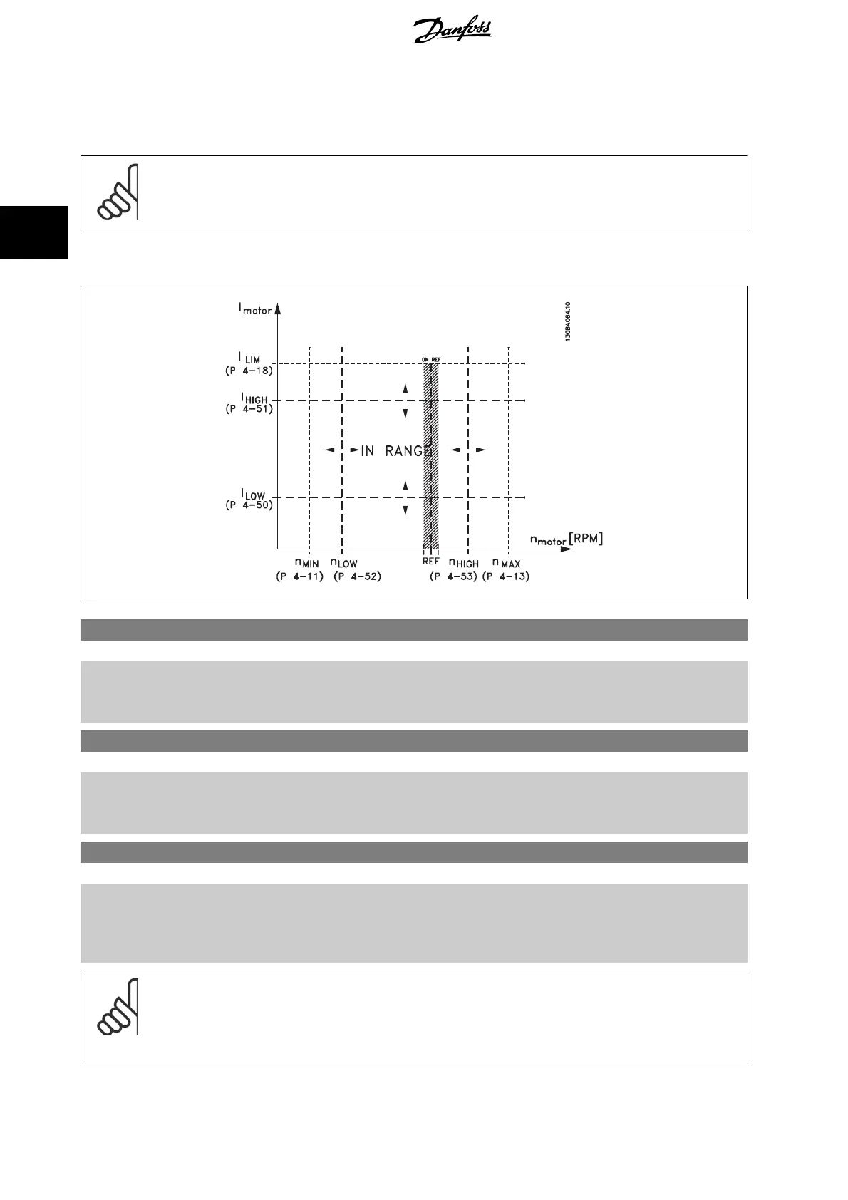
4-50 Warning Current Low
Range: Function:
0.00 A* [Application dependant] Enter the I
LOW
value. When the motor current falls below this limit (I
LOW
), the display reads CURRENT
LOW. The signal outputs can be programmed to produce a status signal on terminal 27 or 29 and
on relay output 01 or 02. Refer to the drawing in this section.
4-51 Warning Current High
Range: Function:
Application
dependent*
[Application dependant] Enter the I
HIGH
value. When the motor current exceeds this limit (I
HIGH
), the display reads CURRENT
HIGH. The signal outputs can be programmed to produce a status signal on terminal 27 or 29 and
on relay output 01 or 02. Refer to the drawing in this section.
4-53 Warning Speed High
Range: Function:
Application
dependent*
[Application dependant] Enter the n
HIGH
value. When the motor speed exceeds this limit (n
HIGH
), the display reads SPEED
HIGH. The signal outputs can be programmed to produce a status signal on terminal 27 or 29 and
on relay output 01 or 02. Programme the upper signal limit of the motor speed, n
HIGH
, within the
normal working range of the frequency converter. Refer to the drawing in this section.
NB!
Any changes in par. 4-13
Motor Speed High Limit [RPM]
will reset the value in par. 4-53
Warning Speed High
to the same value as set
in par. 4-13
Motor Speed High Limit [RPM]
.
If a different value is needed in par. 4-53
Warning Speed High
, it must be set after programming of par. 4-13
Motor Speed High Limit
[RPM]
3 Parameter Description VLT
®
HVAC Drive Programming Guide
74
MG.11.C9.02 - VLT
®
is a registered Danfoss trademark
3