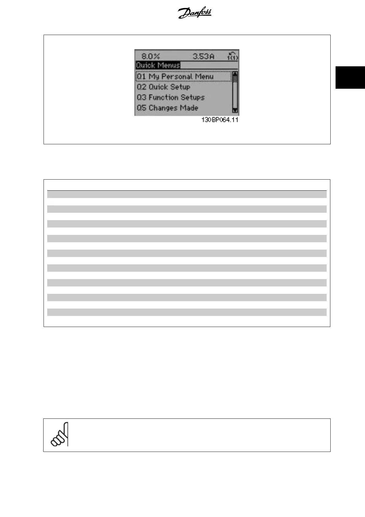
Illustration 2.6: Quick Menu view.
The Quick Setup menu gives access to the 18 most important setup parameters of the frequency converter. After programming the frequency converter
will, in most cases, be ready for operation. The 18 Quick Setup parameters are shown in the table below. A complete description of the function is given
in the parameter description sections of this manual.
Parameter
[Units]
Par. 0-01
Language
Par. 1-20
Motor Power [kW]
[kW]
Par. 1-21
Motor Power [HP]
[HP]
Par. 1-22
Motor Voltage
*[V]
Par. 1-23
Motor Frequency
[Hz]
Par. 1-24
Motor Current
[A]
Par. 1-25
Motor Nominal Speed
[RPM]
Par. 1-28
Motor Rotation Check
[Hz]
Par. 3-41
Ramp 1 Ramp Up Time
[s]
Par. 3-42
Ramp 1 Ramp Down Time
[s]
Par. 4-11
Motor Speed Low Limit [RPM]
[RPM]
Par. 4-12
Motor Speed Low Limit [Hz]
*[Hz]
Par. 4-13
Motor Speed High Limit [RPM]
[RPM]
Par. 4-14
Motor Speed High Limit [Hz]
*[Hz]
Par. 3-19
Jog Speed [RPM]
[RPM]
Par. 3-11
Jog Speed [Hz]
*[Hz]
Par. 5-12
Terminal 27 Digital Input
Par. 5-40
Function Relay
**
Table 2.1: Quick Setup parameters
*The display showing depends on choices made in par. 0-02
Motor Speed Unit
and par. 0-03
Regional Settings
. The default settings of par. 0-02
Motor
Speed Unit
and par. 0-03
Regional Settings
depend on which region of the world the frequency converter is supplied to but can be re-programmed as
required.
** Par. 5-40
Function Relay
, is an array, where one may choose between Relay1 [0] or Relay2 [1]. Standard setting is Relay1 [0] with the default choice
Alarm [9].
See the parameter description in the section
Commonly Used Parameters
.
For a detailed information about settings and programming, please see the
VLT HVAC Drive Programming Guide, MG.11.CX.YY
x=version number y=language
NB!
If [No Operation] is selected in par. 5-12
Terminal 27 Digital Input
, no connection to +24 V on terminal 27 is necessary to enable start.
If [Coast Inverse] (factory default value) is selected in par. 5-12
Terminal 27 Digital Input
, a connection to +24V is necessary to enable
start.
VLT
®
HVAC Drive Programming Guide 2 How to Programme
MG.11.C9.02 - VLT
®
is a registered Danfoss trademark
23
2