25-06 Number of Pumps
Range: Function:
2 N/A* [Application dependant] The number of pumps connected to the Cascade Controller including the variable speed pump. If
the variable speed pump is connected directly to the frequency converter and the other fixed speed
pumps (lag pumps) are controlled by the two built in relays, three pumps can be controlled If both
the variable speed and fixed speed pumps are to be controlled by built-in relays, only two pumps
can be connected.
If
par. 25-05 Fixed Lead Pump, Fixed Lead Pump
, is set to
No
[0]: one variable speed pump and
one fixed speed pump; both controlled by built in relay. If
par. 25-05 Fixed Lead Pump, Fixed Lead
Pump
, is set to
Yes
[1]: one variable speed pump and one fixed speed pump controlled by built-in
relay.
One lead pump, see par. 25-05
Fixed Lead Pump
. Two fixed speed pumps controlled by built-in
relays.
3.23.3 25-2* Bandwidth Settings
Parameters for setting the bandwidth within which the pressure will be allowed to operate before staging/destaging fixed speed pumps. Also includes
various timers to stabilize the control.
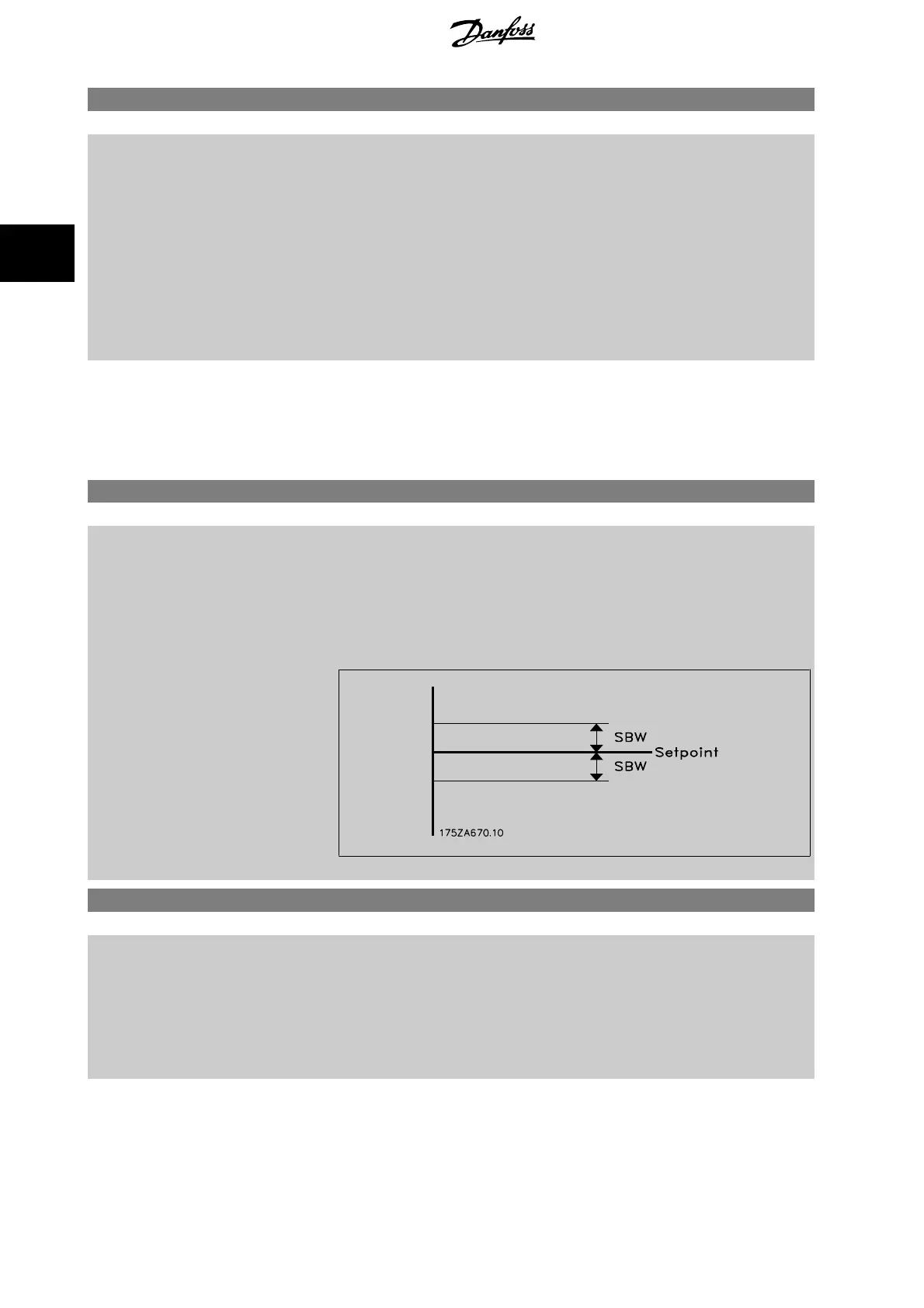
25-20 Staging Bandwidth
Range: Function:
10 %* [Application dependant] Set the staging bandwidth (SBW) percentage to accommodate normal system pressure fluctuation.
In cascade control systems, to avoid frequent switching of fixed speed pumps, the desired system
pressure is typically kept within a bandwidth rather than at a constant level.
The SBW is programmed as a percentage of par. 20-13
Minimum Reference/Feedb.
and
par. 20-14
Maximum Reference/Feedb.
. For example, if the set-point is 5 bar and the SBW is set to
10%, a system pressure between 4.5 and 5.5 bar is tolerated. No staging or de-staging will occur
within this bandwidth.
25-21 Override Bandwidth
Range: Function:
100 %* [Application dependant] When a large and quick change in the system demand occurs (such as a sudden water demand),
the system pressure rapidly changes and an immediate staging or destaging of a fixed speed pump
becomes necessary to match the requirement. The override bandwidth (OBW) is programmed to
override the staging/destaging timer (par. 25-23
SBW Staging Delay
and par. 25-24
SBW Destaging
Delay
) for immediate response.
The OBW must always be programmed to a higher value than the value set in
Staging Bandwidth
(SBW), par. 25-20
Staging Bandwidth
. The OBW is a percentage of par. and par. .
3 Parameter Description VLT
®
HVAC Drive Programming Guide
242
MG.11.C9.02 - VLT
®
is a registered Danfoss trademark
3

 Loading...


