3-56 Ramp 2 S-ramp Ratio at Accel. End
Range: Function:
50 %* [Application dependant] Enter the proportion of the total ramp-up time (par. 3-51
Ramp 2 Ramp up Time
) in which the
acceleration torque decreases. The larger the percentage value, the greater the jerk compensation
achieved, and thus the lower the torque jerks in the application.
3-57 Ramp 2 S-ramp Ratio at Decel. Start
Range: Function:
50 %* [Application dependant] Enter the proportion of the total ramp-down time (par. 3-52
Ramp 2 Ramp down Time
) where the
deceleration torque increases The larger the percentage value, the greater the jerk compensation
achieved, and thus the lower the torque jerks in the application.
3-58 Ramp 2 S-ramp Ratio at Decel. End
Range: Function:
50 %* [Application dependant] Enter the proportion of the total ramp-down time (par. 3-52
Ramp 2 Ramp down Time
) where the
deceleration torque decreases. The larger the percentage value, the greater the jerk compensation
achieved, and thus the lower the torque jerks in the application.
3.5.5 3-8* Other Ramps
Configure parameters for special ramps e.g. Jog or Quick Stop.
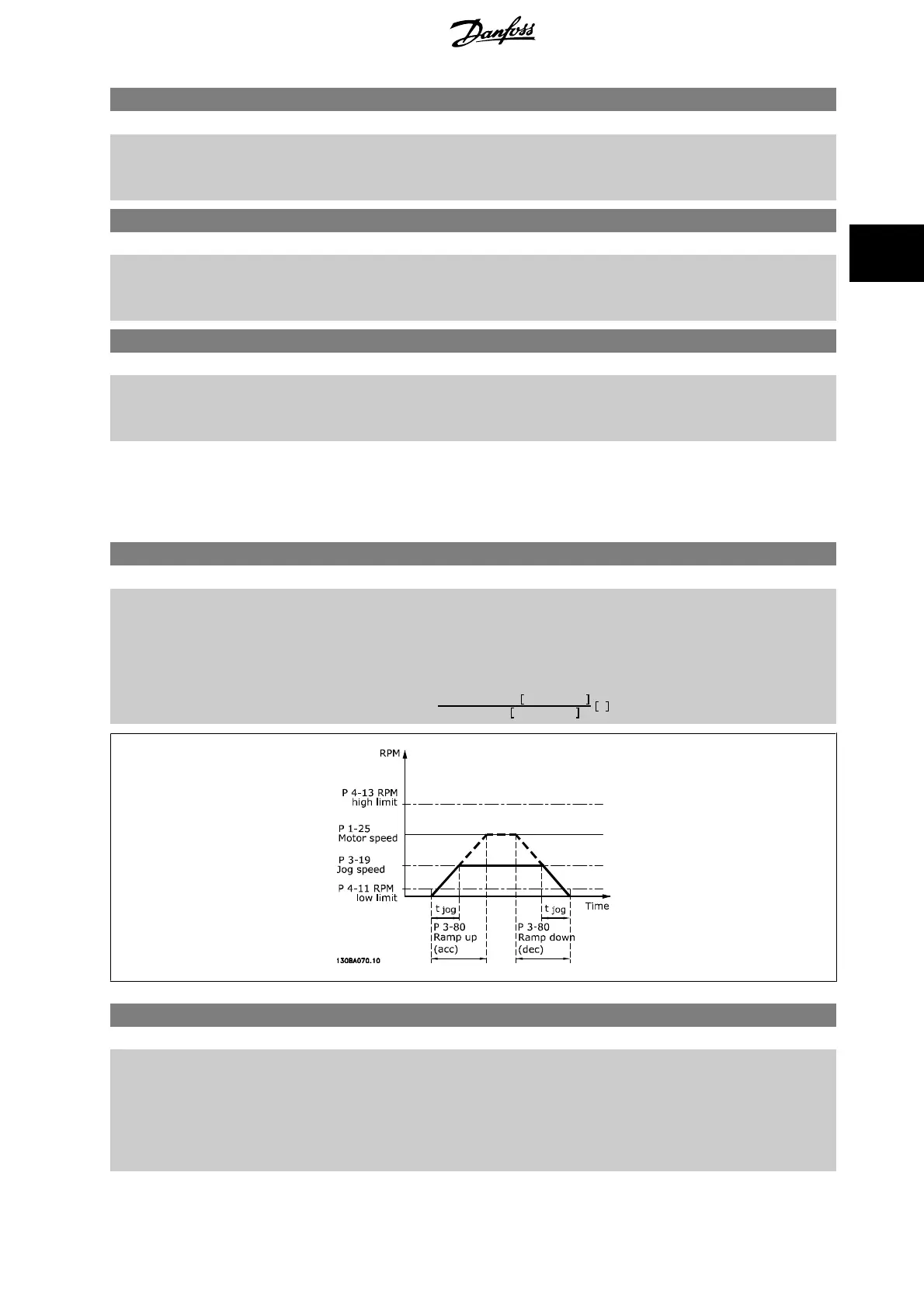
3-80 Jog Ramp Time
Range: Function:
Application
dependent*
[1.00 - 3600.00 s] Enter the jog ramp time, i.e. the acceleration/deceleration time between 0 RPM and the rated motor
speed (n
M,N
) (set in par. 1-25
Motor Nominal Speed
). Ensure that the resultant output current re-
quired for the given jog ramp time does not exceed the current limit in par. 4-18
Current Limit
. The
jog ramp time starts upon activation of a jog signal via the control panel, a selected digital input,
or the serial communication port.
par
. 3 − 80 =
tjog
×
nnorm
par
. 1 − 25
jog
speed
par
. 3 − 19
s
3-81 Quick Stop Ramp Time
Range: Function:
Application
dependent*
[0.01 - 3600.00 s] Enter the quick–stop ramp-down time, i.e. the deceleration time from the synchronous motor speed
to 0 RPM. Ensure that no resultant over-voltage will arise in the inverter due to regenerative oper-
ation of the motor required to achieve the given ramp-down time. Ensure also that the generated
current required to achieve the given ramp-down time does not exceed the current limit (set in
par. 4-18
Current Limit
). Quick-stop is activated by means of a signal on a selected digital input, or
via the serial communication port.
VLT
®
HVAC Drive Programming Guide 3 Parameter Description
MG.11.C9.02 - VLT
®
is a registered Danfoss trademark
69
3

 Loading...


