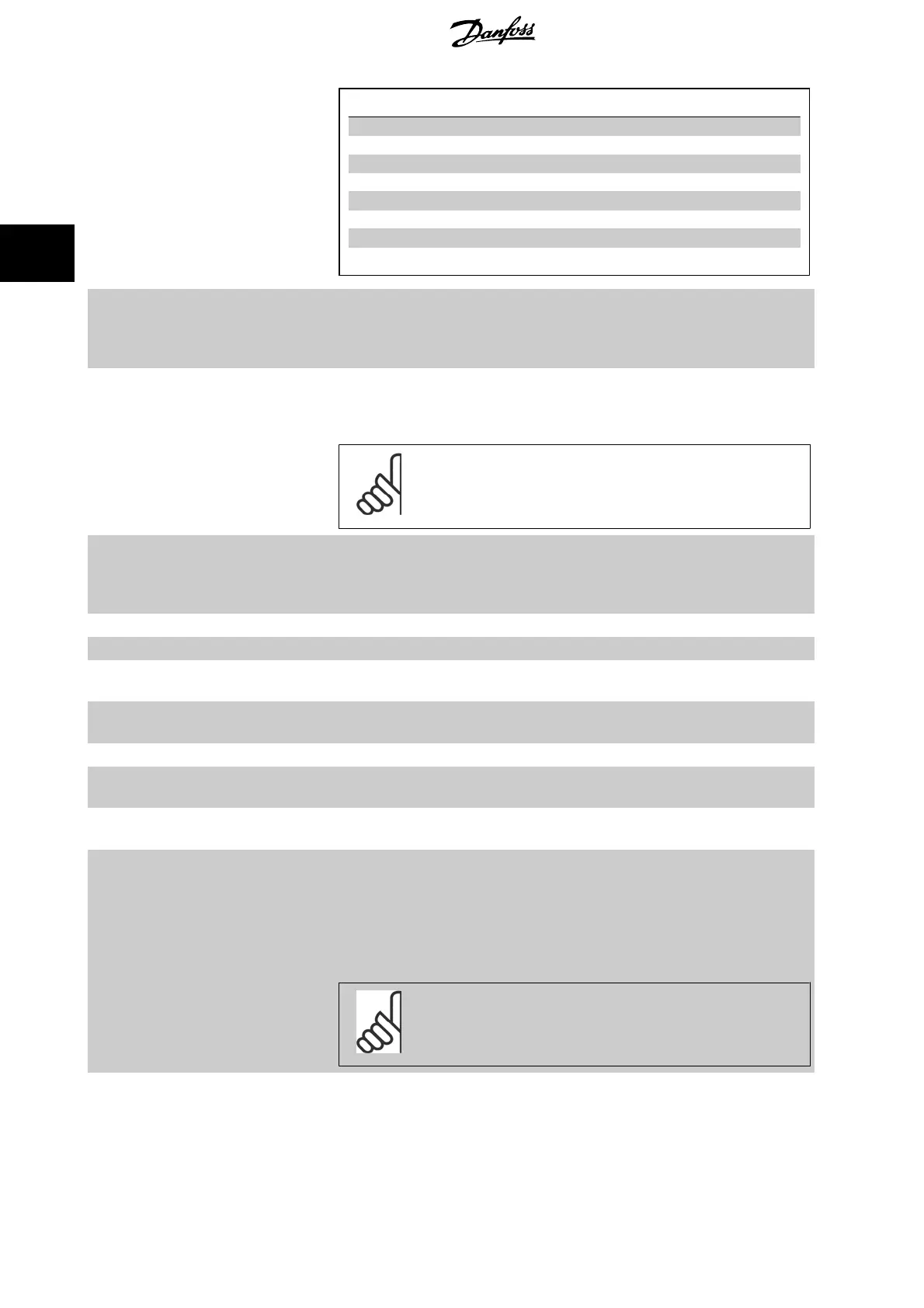
Preset ref. bit 2 1 0
Preset ref. 0 0 0 0
Preset ref. 1 0 0 1
Preset ref. 2 0 1 0
Preset ref. 3 0 1 1
Preset ref. 4 1 0 0
Preset ref. 5 1 0 1
Preset ref. 6 1 1 0
Preset ref. 7 1 1 1
[19] Freeze ref Freezes actual reference. The frozen reference is now the point of enable/condition for Speed up
and Speed down to be used. If Speed up/down is used, the speed change always follows ramp 2
(par. 3-51
Ramp 2 Ramp Up Time
and par. 3-52
Ramp 2 Ramp Down Time
) in the range 0 -
par. 3-03
Maximum Reference
. (For closed loop see par. 20-14
Maximum Reference/Feedb.
).
[20] Freeze output Freezes actual motor frequency (Hz). The frozen motor frequency is now the point of enable/con-
dition for Speed up and Speed down to be used. If Speed up/down is used, the speed change always
follows ramp 2 (par. 3-51
Ramp 2 Ramp Up Time
and par. 3-52
Ramp 2 Ramp Down Time
) in the
range 0 - par. 1-23
Motor Frequency
.
NB!
When Freeze output is active, the frequency converter cannot be stopped via a
low ‘start [13]’ signal. Stop the frequency converter via a terminal programmed
for Coasting inverse [2] or Coast and reset, inverse [3].
[21] Speed up For digital control of the up/down speed is desired (motor potentiometer). Activate this function by
selecting either Freeze reference or Freeze output. When Speed up is activated for less than 400
msec. the resulting reference will be increased by 0.1 %. If Speed up is activated for more than 400
msec. the resulting reference will ramp according to Ramp 1 in par. 3-41
Ramp 1 Ramp Up Time
.
[22] Speed down Same as Speed up [21].
[23] Set-up select bit 0 Selects one of the four set-ups. Set par. 0-10 to Multi Set-up.
[24] Set-up select bit 1 Same as Set-up select bit 0 [23].
(Default Digital input 32)
[32] Pulse input Select Pulse input when using a pulse sequence as either reference or feedback. Scaling is done in
par. group 5-5*.
[34] Ramp bit 0 Select which ramp to use. Logic “0” will select ramp 1 while logic “1” will select ramp 2.
[36] Mains failure inverse Select to activate function selected in par. 14-10
Mains Failure
. Mains failure is active in the Logic
“0” situation.
[37] Fire mode A signal applied will put the frequency converter into Fire Mode and all other commands will be
disregarded. See 24-0*
Fire Mode
.
[52] Run Permissive The input terminal, for which the Run permissive has been programmed must be logic “1” before a
start command can be accepted. Run permissive has a logic ‘AND’ function related to the terminal
which is programmed for
START
[8],
Jog
[14] or
Freeze Output
[20], which means that in order to
start running the motor, both conditions must be fulfilled. If Run Permissive is programmed on
multiple terminals, Run permissive needs only be logic ‘1’ on one of the terminals for the function
to be carried out. The digital output signal for Run Request (
Start
[8],
Jog
[14] or
Freeze output
[20]) programmed in par. 5-3*, or par. 5-4*, will not be affected by Run Permissive.
NB!
If no Run Permissive signal is applied but either Run, Jog or Freeze commands
is activated, the status line in the display will show either Run Requested, Jog
Requested or Freeze Requested.
[53] Hand start A signal applied will put the frequency converter into Hand mode as if button
Hand On
on the LCP
has been pressed and a normal stop command will be overridden. If disconnecting the signal, the
motor will stop. To make any other start commands valid, another digital input must be assign to
Auto Start
and a signal applied to this. The
Hand On
and
Auto On
buttons on the LCP has no impact.
3 Parameter Description VLT
®
HVAC Drive Programming Guide
80
MG.11.C9.02 - VLT
®
is a registered Danfoss trademark
3