Parameter Default Description
Curve select (7142)* f
The Y-axis for the droop curve is frequency. Select U for voltage-dependent
droop.
Curve enable (7143)* Disable
Note that you the droop curve function is disabled by default. Change this
parameter to enable it.
Recovery delay (new)* 600 s
The timer starts when the grid frequency returns to the deadband. The
controller uses power ramp 3 until this timer runs out, or the frequency moves
out of the deadband.
Power ramp 3 is only available if you have Option A10. You can adjust it using
parameters 2801 and 2802.
Calculation method* P installed Selection of actual P or nominal P is to be used as base for the calculations.
Droop slope calculation
method
Absolute Calculation method for the gradient.
Slope low 5 % power/% f/U Gradient during grid under-frequency or under-voltage.
Slope high -5 % power/% f/U Gradient during grid over-frequency or over-voltage.
*Note: Use the USW to configure these parameters, under Advanced Protection, Droop curve 1.
**Note: If Scaling (parameter 9030) is 100 to 25 000 V.
More information
Droop curve 1 is also used by Option A10. Compliance with new grid code rules are possible with AGC controllers and
Option A10. For a more detailed explanation of droop curve 1, see Over- and under-frequency-dependent active power
in Option A10 for more information.
Example
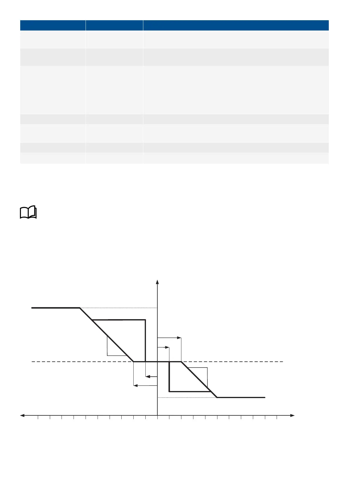
With a nominal frequency of 50 Hz and an actual frequency of 51.5 Hz, there is a deviation of 1.5 Hz which is equal to a 3 %
deviation from the nominal setting. The genset will then droop to 400 kW according to the diagram below.
P [kW]
MAX
DBH
HYSH
Fixed Power Set Point
SLPH
MIN
DBL
HYSL
SLPL
10%
(Fnom-fact)*100/fact [%]
8% 6% 4% 2% 0% 2% 4% 6% 10%8%
The curve can be designed inside MIN/MAX [kW] area.
DESIGNER'S HANDBOOK 4189341275A EN Page 136 of 196

 Loading...


