5. Synchronisation
5.1 Synchronisation principles
The controller can be used for synchronisation of generator and mains breaker (if installed). Two different synchronisation principles
are available, namely static and dynamic synchronisation (dynamic is selected by default). This chapter describes the principles of
the synchronisation functions and the adjustment of them.
INFO
In the following, the term "synchronisation" means "synchronising and closing of the synchronised breaker".
5.2 Dynamic synchronisation
In dynamic synchronisation, the synchronising genset is running at a different speed than the generator on the busbar. This speed
difference is called slip frequency. Typically, the synchronising genset is running with a positive slip frequency. This means that it is
running with a higher speed than the generator on the busbar. The objective is to avoid a reverse power trip after the
synchronisation.
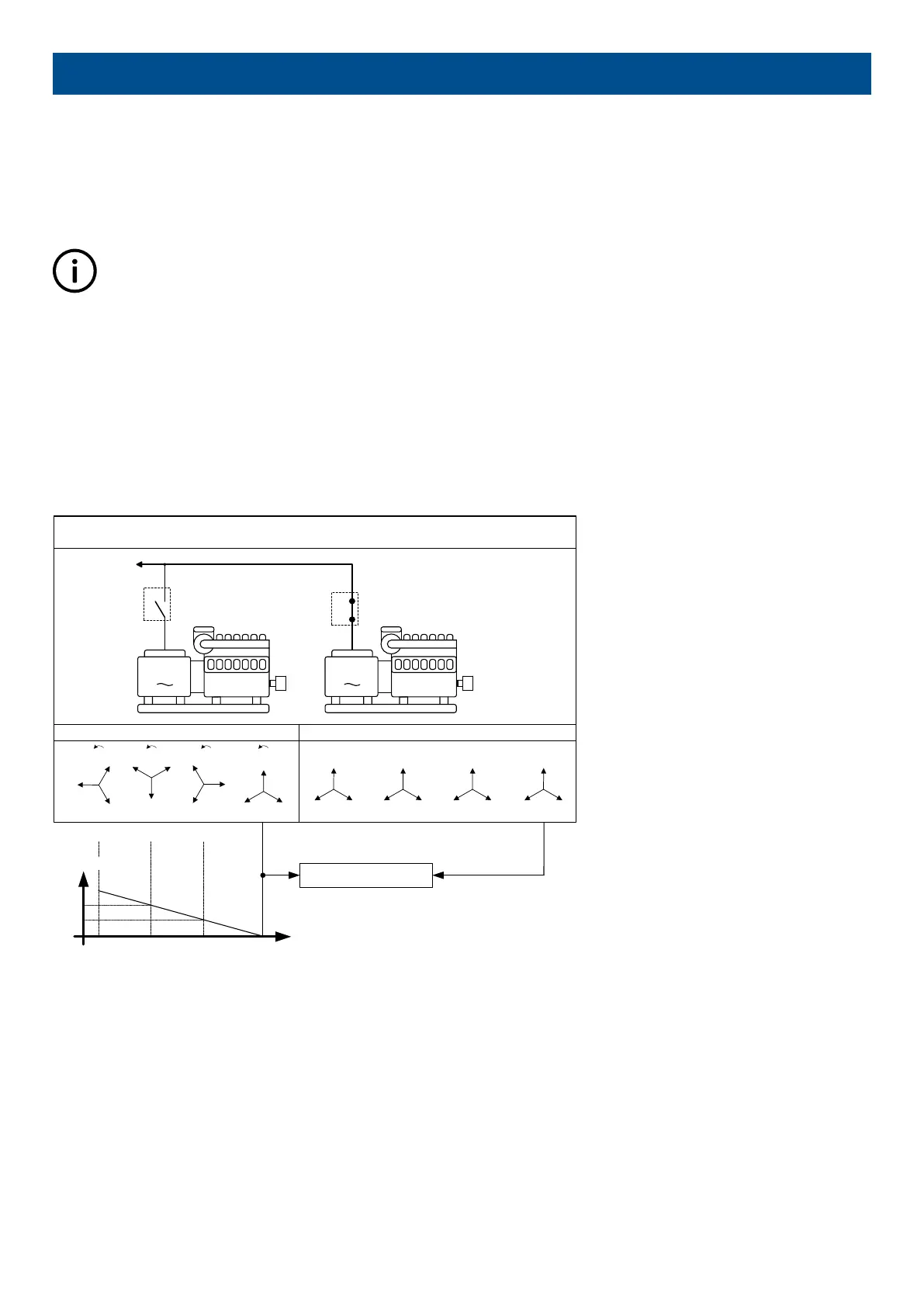
The dynamic principle is illustrated below.
Synchronised
Synchronisation principle – dynamic synchronisation
Speed:
1503 RPM
50.1 Hertz
Speed:
1500 RPM
50.00 Hertz
LOAD
G
GB
G
GB
L1
L2L3
L1
L2L3
L1
L2L3
L1
L2L3
Generator on loadSynchronising generator
L1
L2L3
L1
L2
L3
L1
L2 L3
L1
L2
L3
2.5 s 7.5 s5.0 s0 s
∆t [s]
180°
90°
0°
Angle
L1
gen
/L1
bus
[deg]
In the example above, the synchronising genset is running at 1503 RPM ~ 50.1 Hz. The generator on load is running at 1500 RPM ~
50.0 Hz. This gives the synchronising genset a positive slip frequency of 0.1 Hz.
The intention of the synchronising is to decrease the phase angle difference between the two rotating systems. These two systems
are the three-phase system of the generator and the three-phase system of the busbar. In the illustration above, phase L1 of the
busbar is always pointing at 12 o’clock, whereas phase L1 of the synchronising genset is pointing in different directions due to the
slip frequency.
DESIGNER'S HANDBOOK 4189341275A EN Page 85 of 196

 Loading...


