5.3.2 Close signal
The close signal will be issued when phase L1 of the synchronising generator is close to the 12 o’clock position compared to the
busbar which is also in 12 o’clock position. It is not relevant to use the response time of the circuit breaker when using static
synchronisation, because the slip frequency is either very small or non-existing.
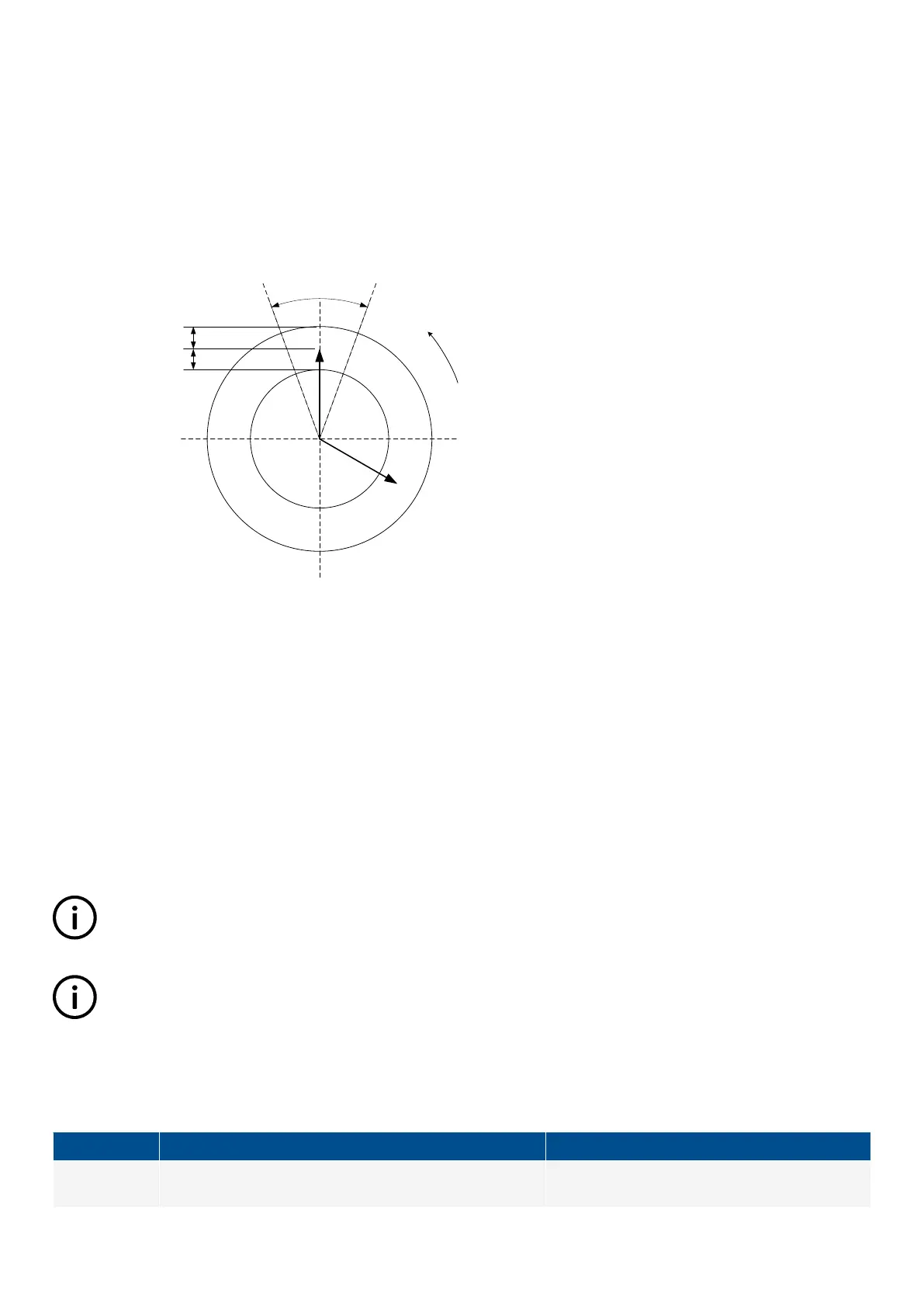
To be able to get a faster synchronisation, a "close window" can be adjusted. The close signal can be issued when the phase angle
U
GENL1
-U
BBL1
is within the adjusted set point. The range is +/-0.1-20.0 deg. This is illustrated in the drawing below.
± close window
Max. dU difference
Max. dU difference
U
BB
U
GEN
Direction of
rotation
The synchronisation pulse is sent dependent on the settings in menu 2030. It depends on whether it is the GB or the MB that is to
be synchronised.
5.3.3 Load picture after synchronisation
The synchronised genset will not be exposed to an immediate load after the breaker closure if the maximum df setting is adjusted to
a low value. Since the fuel rack position almost exactly equals what is required to run at the busbar frequency, no load jump will
occur.
If the maximum df setting is adjusted to a high value, then the observations in the section about "dynamic synchronisation" must be
observed.
After the synchronising, the controller will change the set point according to the requirements of the selected genset mode.
INFO
Static synchronisation is recommended where a slip frequency is not accepted, for instance if several gensets synchronise
to a busbar with no load groups connected.
INFO
Static and dynamic synchronisation can be switched by using M-Logic.
5.3.4 Adjustments
The following settings must be adjusted if the static synchroniser is selected in menu 2000:
Setting
Description Comment
2031
The maximum allowed frequency difference between the
busbar/mains and the generator.
+/- value.
DESIGNER'S HANDBOOK 4189341275A EN Page 89 of 196

 Loading...


