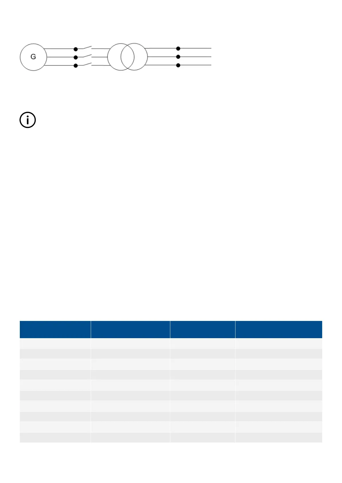
setting in the ML-2, as long as the breaker and the step-up transformer are both placed between the generator and busbar, and
mains voltage measuring points for the ML-2. The measuring points are shown as black dots in the figures above and below.
The phase angle compensation would not be an issue if there was no phase angle shift across the step-up transformer, but in many
cases there is. In Europe, the phase angle shift is described using the vector group description. Instead of vector group, this could
also be called clock notation or phase shift.
INFO
When voltage measurement transformers are used, these must be included in the total phase angle compensation.
When an ML-2 is used for synchronising, the device uses the ratio of the nominal voltages for the generator and the busbar, to
calculate a set point for the AVR and the voltage synchronising window (dU
MAX
).
Example
A 10000 V/400 V step-up transformer is installed after a generator with the nominal voltage of 400 V. The nominal voltage of the
busbar is 10000 V. Now, the voltage of the busbar is 10500 V. The generator is running 400 V before synchronising starts, but when
attempting to synchronise, the AVR set point will be changed to:
U
BUS-MEASURED
× U
GEN-NOM
/U
BUS-NOM
= 10500 × 400/10000 = 420 V
6.44.2 Vector group for step-up transformer
Vector group definition
The vector group is defined by two letters and a number:
• The first letter is an upper case D or Y, defining if the HV side windings are in delta or wye configuration.
• The second letter is a lower case d, y or z, defining if the LV side windings are in delta, wye or zigzag configuration.
• The number is the vector group number, defining the phase angle shift between HV and LV side of the step-up transformer. The
number is an expression of the LV side lag compared to the HV side voltage. The number is an expression of the lag angle
divided by 30 degrees.
Example
Dy11 = HV side: Delta, LV side: Wye, vector group 11: Phase shift = 11 × (–30) = -330 degrees.
Typical vector groups
Vector group
Clock notation Phase shift
LV lag degrees
compared to HV
0 0 0 ° 0 °
1 1 -30 ° 30 °
2 2 -60 ° 60 °
4 4 -120 ° 120 °
5 5 -150 ° 150 °
6 6 -180 °/180 ° 180 °
7 7 150 ° 210 °
8 8 120 ° 240 °
10 10 60 ° 300 °
11 11 30 ° 330 °
DESIGNER'S HANDBOOK 4189341275A EN Page 170 of 196
 Loading...


