INFO
Of course both three-phase systems are rotating, but for illustrative purposes the vectors for the generator on load are not
shown to be rotating. This is because we are only interested in the slip frequency for calculating when to release the
synchronisation pulse.
When the generator is running with a positive slip frequency of 0.1 Hz compared to the busbar, the two systems will be synchronised
every 10 seconds.
INFO
Observe the chapter regarding PID controllers and the synchronising controllers.
In the illustration above, the difference in the phase angle between the synchronising set and the busbar gets smaller and will
eventually be zero. Then the genset is synchronised to the busbar, and the breaker will be closed.
5.2.1 Close signal
The controller always calculates when to close the breaker to get the most accurate synchronisation. This means that the close
breaker signal is actually issued before being synchronised (read L1 phases exactly at 12 o’clock).
The breaker close signal will be issued depending on the breaker closing time and the slip frequency (response time of the circuit
breaker is 250 ms, and the slip frequency is 0.1 Hz):
• deg
CLOSE
= 360 × t
CB
× f
SLIP
• deg
CLOSE
= 360 × 0.250 × 0.1
• deg
CLOSE
= 9 deg
INFO
The synchronisation pulse is always issued, so the closing of the breaker will occur at the 12 o’clock position.
The length of the synchronisation pulse is the response time of the breaker + 20 ms.
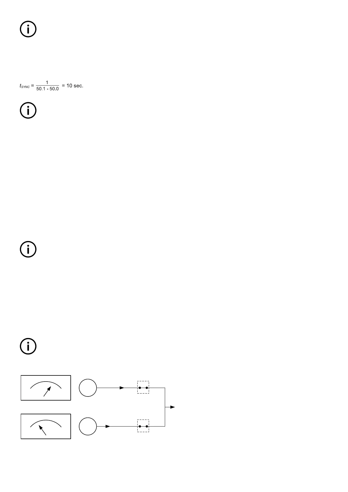
5.2.2 Load picture after synchronising
When the incoming genset has closed its breaker, it will take a portion of the load dependent on the actual position of the fuel rack.
Illustration 1 below indicates that at a given positive slip frequency, the incoming genset will export power to the load. Illustration 2
below shows that at a given negative slip frequency, the incoming genset will receive power from the original genset. This
phenomenon is called reverse power.
INFO
To avoid nuisance trips caused by reverse power, the synchronising settings can be set up with a positive slip frequency.
POSITIVE slip frequency
LOAD
0% 100%
FUEL INDEX
0% 100%
FUEL INDEX
G1
G2
P
Gen1
P
Gen2
GB
GB
DESIGNER'S HANDBOOK 4189341275A EN Page 86 of 196
 Loading...


