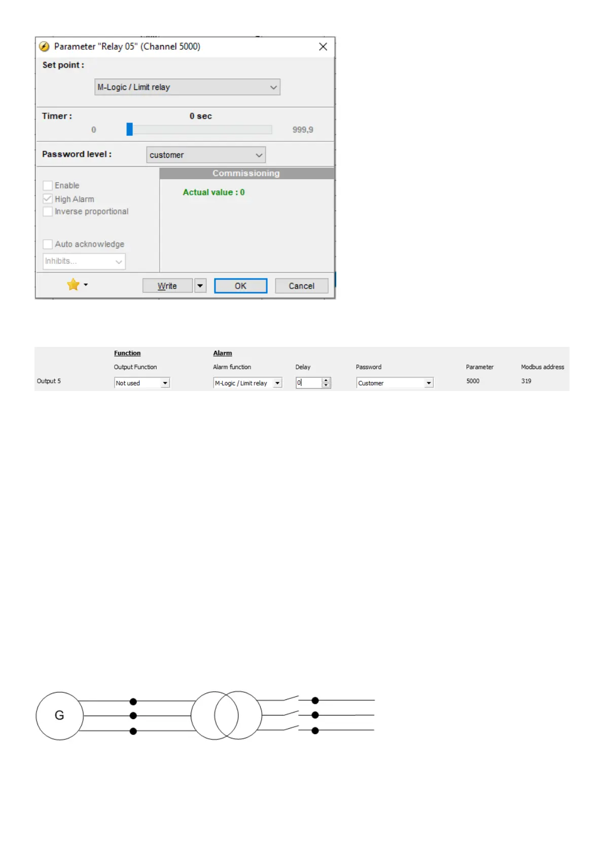
Alternatively, you can configure the relay in the USW under I/O Setup:
The timer in the image above is an OFF delay, meaning that when the alarm level is OK again, the relay will remain activated until
the timer runs out. The timer is only effective when it is configured as M-Logic / Limit relay. If it is configured to any Alarm relay, the
relay is deactivated when the alarm conditions disappear and the alarm is acknowledged.
6.44 Step-up and step-down transformer
6.44.1 Step-up transformer
In certain cases, the use of a generator with step-up transformer (called a block) is required. This may be to adapt to the closest grid
voltage or to step up the voltage to minimise the losses in cables and also to bring down the cable size. The applications where a
step-up transformer is needed, is supported by the ML-2. The functions available in this application are:
1. Synchronising with or without phase angle compensation
2. Voltage measurement displayed
3. Generator protections
4. Busbar protections
A diagram of a block is shown below
Generator/transformer block:
Typically the synchronising breaker is on the high voltage (HV) side, and there is no breaker (or only a manually operated one) on
the low voltage (LV) side. In some applications, the breaker could also be placed on the LV side. But this does not influence on the
DESIGNER'S HANDBOOK 4189341275A EN Page 169 of 196
 Loading...


