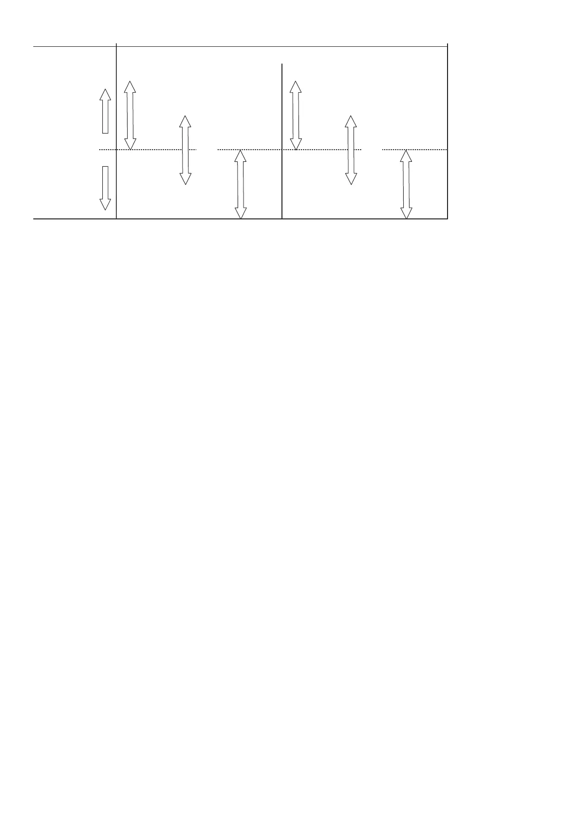
Set point
Below set point
Above set point
Direct Inverse
Analogue offset 100 % 50 % 0 %
Output
Input
100 % 50 % 0 %
0 %
50 %
100 %
0 %
50 %
100 %
0 %
50 %
100 %
100 %
50 %
0 %
100 %
50 %
0 %
100 %
50 %
0 %
100 % offset is commonly used with inverse output, like in the previous cooling example. For an example of other use, see “Example
of inverse output with 0 % offset”.
9: M-Logic min event set point
Determines the output of M-Logic function "PID1 force min. Outp."
10: M-Logic max event set point
Determines the output of M-Logic function "PID1 force max. Outp."
11: Relay Db
Deadband setting for relay control.
12: Relay Kp
Proportional gain value for relay control.
13: Relay Td
Derivative output for relay control.
14: Relay min on-time
Minimum output time for relay control. Set this to the minimum time that is able to activate the controlled actuator.
15: Relay period time
Total time for a relay activation period. When the regulation output is above this period time, the relay output is constantly activated.
17: Relay increase
Choose the terminal for the relay used for positive activation.
18: Relay decrease
Choose the terminal for the relay used for negative activation.
7.4 Kp gain compensation
7.4.1 Introduction
This document describes the functionality regarding the “Kp gain compensation”, so it is possible to utilise the function parameters
and help with setting up the function. This function is intended to be used when the AGC is controlling the cooling water system for
the genset.
As it is today, there are two situations in which the engine is in danger of ending in an oscillation that could shut down the engine:
1. Load impacts
2. Cold start of engine
In both situations, it is desired to have a higher gain when the change is needed, but a lower gain when the system has to stabilise.
Without "Kp gain compensation", the PID settings need to be balanced between reaction and stability. The “Kp gain compensation”
DESIGNER'S HANDBOOK 4189341275A EN Page 189 of 196
 Loading...


