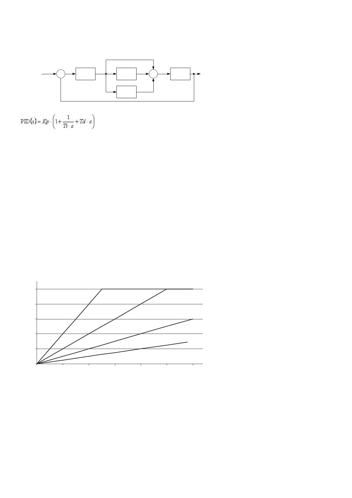
4.3 Principle drawing
The drawing below shows the basic principle of the PID controller.
P-part
(Kp)
I-part
(Ti)
D-part
(Td)
OutputSet point Σ Σ
-
++
+
As illustrated in the above drawing and equation, each regulator (P, I and D) gives an output which is summarised to the total
controller output.
The adjustable settings for the PID controllers in the AGC are:
• Kp: The gain for the proportional part.
• Ti: The integral action time for the integral part.
• Td: The derivative action time for the derivative part.
4.4 Proportional regulator
When the regulation deviation occurs, the proportional part will cause an immediate change of the output. The size of the change
depends on the gain Kp.
The diagram shows how the output of the P regulator depends on the Kp setting. The change of the output at a given Kp setting will
be doubled if the regulation deviation doubles.
P-regulator
Output (%)
100
80
60
40
20
0
0 10 20 30 40 50 60
Kp
4 % 2 %
1 %
0.5 %
4.4.1 Speed range
Because of the characteristic above it is recommended to use the full range of the output to avoid an unstable regulation. If the
output range used is too small, a small regulation deviation will cause a rather big output change. This is shown in the drawing
below.
DESIGNER'S HANDBOOK 4189341275A EN Page 76 of 196
 Loading...


