determines if the ramp 2 is activated by droop or M-Logic. If automatic "ramp selection" is activated, then the second ramp is
enabled during power droop. If it is disabled, then the second ramp can only be activated by M-Logic.
2.4.6 Q ramp
A ramp function for reactive power regulation can be activated. This ramp is used when the controller increases or decreases the
reactive power. Configure these parameters in the USW.
Text Parameter Default Range Description
Q ramp to setp. 2821 2 %/s 0.1 to 20 %/s Ramp up for reactive power
Q ramp to zero 2822 2 %/s 0.1 to 20 %/s Ramp down for reactive power
Q ramp enable 2823 OFF
ON
OFF
Activation/deactivation of the function
INFO
There is no ramp for cos phi regulation.
2.4.7 Fixed power/base load
Auto mode description
The controller automatically starts the genset and synchronises to the mains when the digital input "auto start/stop" is activated.
After the generator breaker closure, the controller ramps up the load to the set point level. When the stop command is given, the
genset is de-loaded and stopped after the cooling down period. The start and stop commands are used by activating and
deactivating a digital input or with the time-dependent start/stop commands. If the time-dependent start/stop commands are to be
used, then the auto mode must also be used.
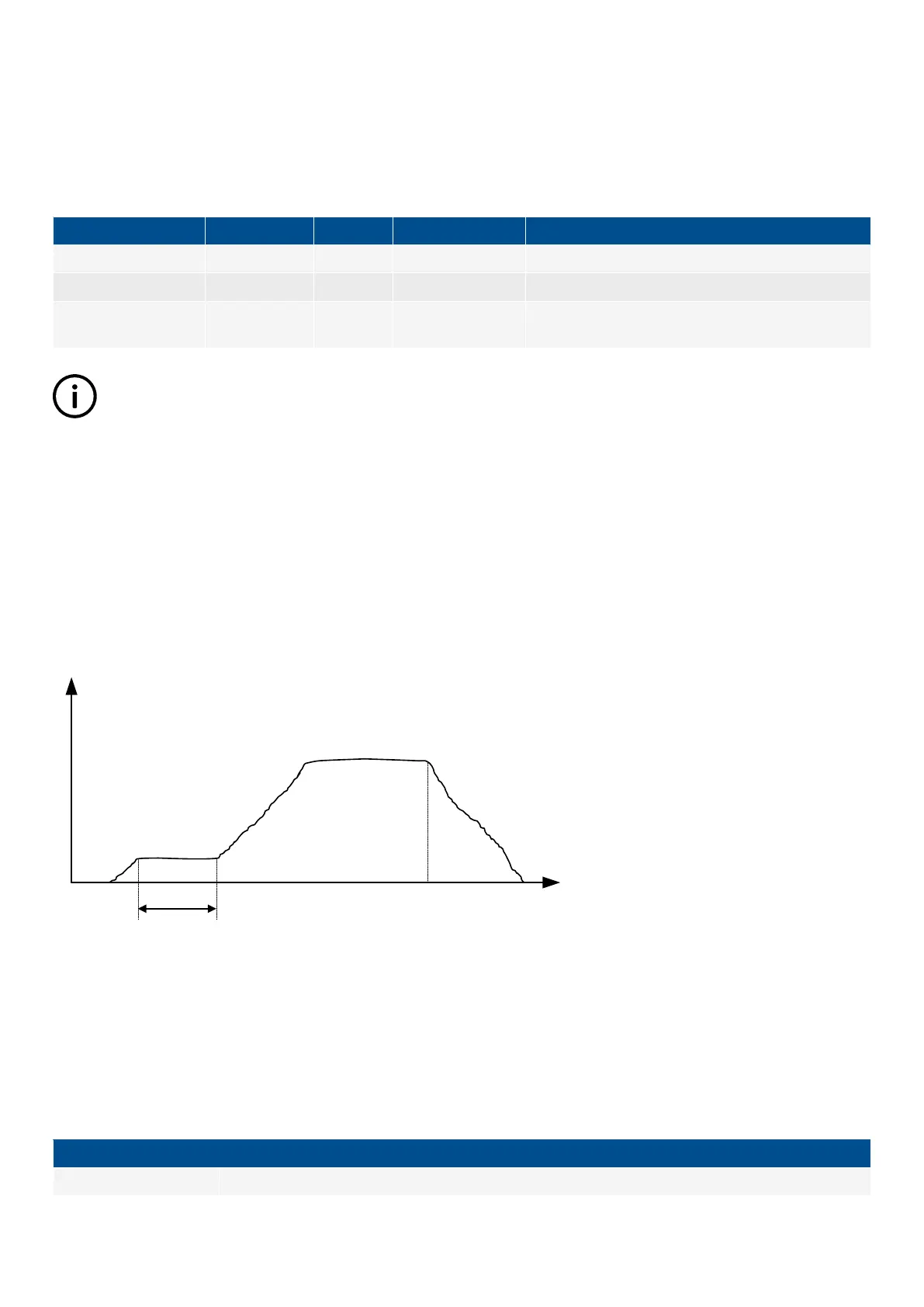
Diagram, fixed power - principle
kW
Start signal
Stop signal
t
RAMP-UP
t
Semi-auto mode description
When the generator breaker is closed and the mains breaker is opened, the controller will use the nominal frequency as the set
point for the speed governor. If AVR control is used, the nominal voltage is used as set point.
When the generator is paralleled to the mains, the generator power will be increased to the fixed power set point. If AVR control is
used, then the set point will either be adjusted power factor or reactive power (7050 Fixed power set).
7050 Fixed Power Set
Power set The amount of power the genset will produce.
DESIGNER'S HANDBOOK 4189341275A EN Page 20 of 196
 Loading...


